LIN bus communication is a low-cost, single-wire automotive networking method in which one commander schedules predictable messages and responder nodes exchange data for localized sensors, switches, motors, and actuators. LIN normally operates beneath CAN, trading bandwidth and flexibility for simpler hardware, lower cost, and deterministic scheduling.
That design makes LIN common in body electronics and mechatronic subsystems, but LIN is not simply a slower CAN bus. Its electrical layer, commander-led schedule, frame format, checksum rules, and cluster-specific LDF all determine how a vehicle network behaves.
As an Amazon Associate I earn from qualifying purchases.
Key takeaways
- LIN is a low-cost, single-wire automotive network designed for localized sensors, switches, motors, actuators, and mechatronic functions.
- A LIN cluster normally has one commander and multiple responders, and the commander initiates every scheduled transaction.
- A LIN frame consists of a Break, delimiter, fixed
0x55Sync byte, Protected Identifier, data response, and checksum. - The cited manufacturer documentation specifies communication up to 20 kbit/s; a Texas Instruments application note discusses one commander, up to 16 responders, and a 40 m harness limit for its defined configuration.
- A LIN node normally combines an MCU UART or SCI peripheral with a dedicated LIN transceiver rather than connecting the MCU directly to the vehicle bus.
What is LIN bus communication?
LIN bus communication is a low-cost, single-wire automotive networking method in which one commander schedules predictable messages and responder nodes exchange data for localized sensors, switches, motors, and actuators. LIN normally operates beneath a higher-level network such as CAN, trading bandwidth and flexibility for simpler hardware, lower cost, and deterministic scheduling.
Microchip describes LIN as a low-cost serial communications protocol used mostly in automotive networks. Microchip’s implementation note also characterizes LIN as a “low cost, short distance, low speed network” intended for events that occur on human time scales.
#1 Best Overall

- CAN Mode: Automatic regonize the direction of CAN-H and CAN-L, can read CAN BUS Baud Range: 50, 83, 100,125,150,200,250,300,400,500,666,800,1000kbps
- LIN Mode: can read LIN BUS Baud Range: 2400-4800-9600-14400-19200bps. Red plug connects to LIN, black plug connects to GND.
- PWM Singal Mode: < 20V PWM singal detector for line.
- View Standard Frames ID data: Easy to stop the ID page to read the part of standard frames data.
- Directly use CAN/LIN/PWM analyzer quickly check if the plug with communication data or not.
Why was LIN created?
LIN was created for vehicle functions that do not need CAN-level throughput, sophisticated peer-to-peer arbitration, or a high-performance distributed control network. Door switches, seat controls, mirror adjustment, small motors, rain or light sensors, climate-control actuators, and similar body-electronics functions are typical examples of localized loads.
In a hierarchical automotive network, CAN or another higher-level bus can connect major electronic control units while LIN clusters connect simpler local devices. The result is a practical division of labor: CAN handles more demanding distributed communication, while LIN handles inexpensive local control.
How does the LIN bus work?
LIN uses a commander-controlled schedule. The commander selects a message by transmitting a header, and the responder assigned to that message either sends the response or receives it. A responder does not normally begin transmitting spontaneously, so the timing and order of bus activity are determined by the commander’s schedule.
Outdated Drivers Are Slowing You Down
One free scan finds every outdated or missing driver and matches the right update for your exact hardware.Free scan · exact hardware matchPC Slower Than It Used to Be?
A free scan shows the junk files, broken settings and background clutter dragging Windows down - then fixes them in one click.Free scan · Windows 10 & 11This approach makes LIN deterministic. CAN allows several nodes to attempt bus access and uses arbitration to determine which message proceeds; LIN avoids that contention by giving one commander responsibility for initiating transactions. The trade-off is that the commander must maintain the schedule and that LIN offers less bandwidth and flexibility.
| Characteristic | LIN | CAN |
|---|---|---|
| Access model | One commander schedules each transaction | Nodes contend for access; arbitration selects the winning message |
| Physical wiring | Single-wire automotive bus with LIN transceivers | Differential CAN bus with CAN transceivers |
| Speed in the cited documentation | Up to 20 kbit/s | Usually much higher, depending on CAN generation and configuration |
| Best-fit role | Localized, predictable, cost-sensitive sensors and actuators | Higher-performance distributed control and ECU networking |
| Main trade-off | Low cost and simplicity, but lower bandwidth and flexibility | More capable, but generally more complex and expensive |
Texas Instruments’ LIN protocol and physical-layer material describes LIN as a low-cost serial protocol based on UART/SCI and commonly used as a sub-bus to CAN. LIN versus CAN is therefore an engineering choice rather than a question of one protocol universally replacing the other.
What are the LIN commander and responder roles?
A conventional LIN cluster has one commander and multiple responders. The commander owns the schedule and sends the header; a responder is associated with a particular message and provides or consumes the response defined for that message.
Older documentation and tools commonly use the terms “master” and “slave.” Current ISO-oriented terminology uses “commander” and “responder,” so both word pairs may appear when reading vehicle service information, software, or datasheets. LIN-CIA’s standards overview documents the terminology change and explains the relationship between the long-established LIN 2.2A terminology and the ISO 17987 standard family.
Rank #2
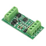
- It is a TTL_UART to for LIN bus module.The module uses TJA1021 IC.It is mainly used for communication monitoring and maintenance for LIN bus equipment.
- The measured baud rate of the module can reach 57600bps,and the recommended maximum operating frequency is less than 20Kbps.
- Power supply anti-reverse connection protection, for LIN bus anti-surge protection
- Compatible with 3.3V/5V microcontroller system
- When the module is connected to the computer's COM port,the computer can receive data,but it cannot communicate with your slave device as a host.The computer's com port cannot generate the 13-bit start bit in the for LIN protocol,but it can be connected to a development board such as a microcontroller.
The original LIN Consortium released Revision 2.2A on December 31, 2010. LIN-CIA’s current standards overview lists 2025 editions for ISO 17987 Parts 1, 2, 3, 4, 6, and 7, while noting that LIN 2.2A remains one of the most implemented versions. A specific vehicle or product may still use an older revision, so the applicable specification must be checked rather than assumed.
What is a LIN frame?
A LIN frame is a commander-sent header followed by a responder-sent response. The header identifies and synchronizes the transaction; the response carries the configured data bytes and checksum.
| Frame field | What it does |
|---|---|
| Break | Marks the beginning of a LIN frame with a dominant interval. |
| Delimiter | Provides a recessive separation between the Break and Sync byte. |
| Sync byte | The fixed 0x55 value provides repeated edges that responders use for bit-rate synchronization. |
| Protected Identifier | Contains the message identifier and its parity bits. |
| Data response | Contains the message’s configured payload bytes. |
| Checksum | Allows the receiver to detect errors in the response according to the configured checksum convention. |
Microchip’s LIN bus-communication documentation specifies a Break of 13 bit times followed by a delimiter of at least one recessive bit. The fixed 0x55 Sync byte is important because it gives responders a repeated edge pattern from which they can adjust timing.
The Protected Identifier is more than a simple label. The cluster configuration determines which message is associated with the identifier, which node should respond, the payload length, and how the bytes map to application signals.
Do these 3 things before closing this tab:
1Clear out junk files and repair common Windows errors2Scan for outdated or missing drivers - takes under a minute3Repair Windows errors before they cause bigger problemsWhat is the difference between LIN classic and enhanced checksum?
The classic LIN checksum covers only the data bytes, while the enhanced LIN checksum covers the data bytes and the Protected Identifier. Older LIN 1.3 devices used the data-only convention more commonly; newer LIN standards use enhanced checksum for applicable messages.
| Checksum mode | Inputs included | Interoperability concern |
|---|---|---|
| Classic | Data bytes only | Expected by older message definitions and some legacy devices |
| Enhanced | Protected Identifier plus data bytes | Must match the message definition and applicable LIN revision |
A capture can contain apparently correct data and still fail validation if the analyzer uses the wrong checksum mode. Also verify the Protected Identifier, payload length, byte order, and signal definition against the cluster description. Microchip’s protocol documentation illustrates both checksum conventions.
What is a LIN transceiver?
A LIN transceiver is the physical-layer IC between an MCU’s UART or SCI controller and the automotive single-wire bus. The transceiver converts logic-level transmit and receive signals into LIN bus signaling and provides the voltage handling, dominant/recessive interface, protection, and bus connection expected by the network.
Rank #3

- 3. Support LIN bus data monitoring function.
- 1. Support the host to send and receive LIN bus data.
- 4. Support LIN bus data playback.
- 2. Support the slave to send and receive LIN bus data (up to 16 channels supported).
- 5. Supports offline sending function. You can burn messages (up to 16) through the host computer without using a computer. After connecting to the power bank for power, you can send LIN messages.
A typical LIN node contains three functional parts:
Quick wins for a faster PC:
Fix the driver behind crashes, sound loss and screen glitchesFind Drivers →Repair Windows errors before they cause bigger problemsFix Now →Scan for outdated or missing drivers - takes under a minuteDriver Scan →- An application MCU or controller.
- A UART, SCI, equivalent LIN peripheral, or software state machine.
- A dedicated LIN transceiver connected to the bus.
A standard MCU UART should not be connected directly to an automotive LIN wire. The bus is not ordinary 3.3 V logic. In the cited Microchip implementation guidance, the bus supply range is 7–18 V, the recessive level is above 60% of VSUP, and the dominant level is below 40% of VSUP. Those values describe that implementation guidance, not a universal substitute for the selected transceiver’s datasheet.
Analog Devices’ MAX13020/MAX13021 documentation illustrates the role of a LIN transceiver between a protocol controller and the LIN physical bus and identifies support for LIN 2.0, SAE J2602, and communication up to 20 kbaud. Choose the actual device for bus voltage, EMC, ESD, wake-up, fault behavior, temperature range, and vehicle requirements.
How fast and how large can a LIN network be?
The cited LIN documentation gives a maximum communication rate of 20 kbit/s. According to Microchip’s 2025 LIN overview, LIN is intended as a low-speed automotive network rather than a high-throughput replacement for CAN.
According to Texas Instruments’ 2022 application note, the defined configuration discusses one commander plus up to 16 responder nodes and a maximum harness length of 40 m. The same application material gives a practical guideline of staying near or below 10 nF total bus capacitance at 20 kbps. These are constraints and guidance for the cited configuration, not blanket permission to apply the values to every transceiver, harness, vehicle, or current ISO design.
What’s actually slowing this PC down?
Pick the symptom - the matching free tool is one click away.
Reliable operation also depends on bus capacitance, pull-up and termination behavior, harness topology, node count, ESD protection, supply integrity, oscillator tolerance, and the selected transceiver. A design that meets the nominal bit rate can still produce slow rising edges or intermittent communication if the physical layer is overloaded.
What is an LDF file?
An LDF, or LIN Description File, is an ASCII configuration file that describes the specific LIN cluster rather than merely describing the generic protocol. The LDF typically contains node information, message identifiers, schedules, signal definitions, timing, and diagnostic-related configuration.
Rank #4

- Multi-version USB compatible, USB to LIN communication
- Supports LIN2.2 protocol and can be used as a master-slave device
- 500V isolation + short circuit protection, DB9 interface
- Automatic identification of bus parameters, multi-frame scheduling
- Dual power supply, with working status indicator light
The LDF is the bridge between raw bus traffic and useful application data. An analyzer can display a Protected Identifier and payload bytes without an LDF, but signal names, scaling, units, publisher/subscriber relationships, and scheduled-message meaning usually require the correct LDF or equivalent OEM documentation.
Microchip’s LIN overview notes that tools can use LDF information to generate ANSI-C driver code and header files. Before decoding a vehicle capture, confirm that the LDF matches the vehicle, model year, ECU variant, and LIN cluster being examined.
How do I read LIN bus data?
To read LIN bus data, capture the single-wire traffic with a compatible LIN interface, confirm the electrical connection and baud rate, then decode the header, identifier, response, checksum mode, and signals using the correct LDF or message documentation.
- Identify the cluster. Determine the vehicle or module, bus supply, connector pinout, ground reference, expected LIN revision, and whether the test point is a complete vehicle network or a bench setup.
- Use the correct interface. A PC tool must support LIN at the required electrical level; a CAN-only interface is not automatically a LIN interface. A documented USB LIN interface can provide PC connectivity and LIN message transmission and reception, but compatibility with a particular vehicle still depends on voltage, connector, software, and protocol configuration.
- Capture the header. Look for the Break, delimiter,
0x55Sync byte, and Protected Identifier. Missing or malformed headers often explain why a responder appears silent. - Decode the response. Check the expected data length and identify which node should publish or consume the response.
- Validate the checksum. Select classic or enhanced checksum according to the message definition, not merely according to what produces a passing result.
- Load the LDF. Use the file to convert raw bytes into signal names, values, scaling, and units. Without the correct LDF, treat decoded signal meanings as unverified.
A compatible LIN connection cable or breakout cable can simplify bench access to LIN, CAN, and supply connections on supported PC interfaces. A cable is only an electrical connection accessory; it does not replace the LIN transceiver or analyzer.
Independent reader supportYour contribution helps us test, update, and keep practical guides available for everyone.How do I implement a LIN node?
A practical LIN implementation starts with the cluster definition and ends with waveform and interoperability testing.
- Define nodes, signals, message identifiers, schedules, timing, and diagnostics.
- Create or obtain the matching LDF.
- Select an MCU with a suitable UART, SCI, or LIN peripheral.
- Select a LIN transceiver for the bus supply, EMC, ESD, wake-up, fault, and temperature requirements.
- Implement commander scheduling or responder behavior.
- Implement Break detection, Sync handling, identifier parity, data processing, and the required checksum mode.
- Validate bus voltage, waveform quality, loading, wake-up behavior, error handling, and physical connections.
- Compare analyzer captures with the expected schedule and LDF.
Official implementation material from Microchip, Texas Instruments, and Analog Devices supports the MCU-plus-transceiver architecture. The exact peripheral configuration, sleep behavior, diagnostics, and error handling depend on the selected MCU, transceiver, LIN revision, and cluster requirements.
Free tools Windows power users keep installed
One-click scans. No signup required.
What should I check when a LIN bus does not work?
| Symptom | Likely checks |
|---|---|
| No responder activity | Bus supply, ground, transceiver enable or sleep state, commander schedule, Protected Identifier, wiring, and whether the responder is actually assigned to that message. |
| Synchronization or framing errors | Break width, delimiter, 0x55 Sync byte, configured baud rate, oscillator tolerance, and transceiver connection. |
| Checksum errors | Classic versus enhanced mode, Protected Identifier parity, payload length, byte order, and LDF/message definition. |
| Distorted edges or intermittent traffic | Total capacitance, harness length, node count, pull-up behavior, ESD protection, supply integrity, and transceiver selection. |
| Raw bytes but no signal names | The correct LDF or OEM message documentation is missing, mismatched, or unavailable. |
A responder normally remains quiet until the commander schedules its identifier, so “no response” is not automatically proof of a failed responder. For synchronization problems, inspect the Break and Sync byte first. For checksum problems, verify the checksum convention and Protected Identifier before investigating the payload.
Best Value

- 【High-Speed 8-Channel Analysis】Captures digital signals at up to 24MHz across 8 channels, enabling precise debugging of complex protocols like I2C, SPI, and UART—ideal for advanced STEM projects without the limitations of basic 4-channel models.
- 【User-Friendly Design】Base module and breakout board simplify connections to breadboards, microcontrollers, and other setups.
- 【Logic Level Expansion Board】Breaks out all 8 channels to 2.54mm male pins and pads for alligator clips, enabling flexible and secure connections in diverse projects.
- 【Logic Level Breadboard Adapter】 Easily connects the logic analyzer to breadboards, providing direct and convenient access to all 8 channels for prototyping and testing.
- 【Dual USB Connectivity】Comes with both USB-A and Type-C cables for universal compatibility with older PCs, modern laptops, and devices, ensuring hassle-free plug-and-play across Windows, Mac, Linux, and Ubuntu.
For physical-layer faults, Texas Instruments’ physical-layer guidance explains why bus capacitance, harness length, and node loading affect rising-edge quality at 20 kbps. Do not treat a software capture as proof that the electrical waveform is healthy.
When should you choose LIN instead of CAN?
Choose LIN when the function is local, low bandwidth, predictable, and cost-sensitive, and when one scheduled commander can coordinate the required responders. Choose CAN when multiple nodes need higher bandwidth, stronger distributed arbitration, or more flexible network behavior.
| Choose LIN when… | Choose CAN when… |
|---|---|
| A switch, sensor, motor, or actuator is physically localized. | Several distributed ECUs need to communicate with greater autonomy. |
| Message timing can be determined by one schedule. | Nodes need flexible bus access and arbitration. |
| Low hardware cost matters more than throughput. | Higher bandwidth and broader networking capability justify greater complexity. |
| The application operates on human-time scales. | The application needs faster or more demanding control communication. |
LIN is not an inferior version of CAN; LIN and CAN solve different networking problems. LIN’s value comes from deliberately limiting complexity where a more capable bus would add cost without providing a useful benefit.
The Tool Desk
Outbyte Driver Updater FREEFix the driver behind crashes, sound loss and screen glitchesFind Drivers →Outbyte PC Repair FREEClear out junk files and repair common Windows errorsFree Scan →Frequently Asked Questions
What is LIN bus communication?
LIN bus communication is a low-cost, single-wire automotive network in which one commander schedules messages and responder nodes exchange data for localized sensors, switches, motors, and actuators. LIN commonly operates as a local sub-bus beneath CAN or another higher-level vehicle network.
What is a LIN frame?
A LIN frame contains a Break, delimiter, fixed 0x55 Sync byte, Protected Identifier, data response, and checksum. The commander sends the header, while the responder assigned to that identifier provides or receives the response.
What is a LIN transceiver?
A LIN transceiver connects an MCU UART or SCI peripheral to the automotive single-wire LIN bus. The transceiver handles the bus’s automotive voltage and dominant/recessive signaling, so a standard MCU UART should not be connected directly to the LIN wire.
What is an LDF file?
An LDF, or LIN Description File, describes a particular cluster’s nodes, identifiers, schedules, signals, timing, and diagnostics. Raw bytes can be captured without an LDF, but meaningful signal names and values usually require the correct LDF or equivalent OEM documentation.
Recommended Free Tools
The Bottom Line
LIN is a deliberately modest automotive network: one commander schedules low-bandwidth traffic, responders provide predictable data, and a UART-plus-transceiver design keeps local nodes inexpensive. Correct operation still depends on the exact LIN revision, LDF, checksum mode, transceiver, harness, bus loading, and electrical validation.
Quick Recap
Product prices and availability are accurate as of the date/time indicated and are subject to change. Any price and availability information displayed on Amazon at the time of purchase will apply.