Do these 3 things before closing this tab:
1Fix the driver behind crashes, sound loss and screen glitches2Repair Windows errors before they cause bigger problems3Scan for outdated or missing drivers - takes under a minuteYou can learn how a motorized monowheel is organized and plan a project around the published designs, but the public record does not contain a build-ready recipe. No published record covered here gives validated dimensions, material grades, component ratings, a safe top speed, or a tested procedure for building and riding one. What follows explains the three documented architectures, what one student build shows about the process, the engineering questions a responsible project has to settle first, and what remains unestablished.
How a monowheel is organized
A monowheel places the rider and a supporting frame inside or alongside one large wheel. The outer wheel, a tire on a rim, rotates around the inner structure, so the designer has to keep that structure positioned and upright while the outer wheel turns, accelerates, brakes and meets bumps. Each published design answers that problem differently, so the useful comparison is how each one handles the same questions.
Three documented design approaches
Three published patent records describe motorized monowheels in enough detail to compare. Each is a design disclosure. None is independent evidence that its machine performs safely.
Roller-supported inner frame with wheel-contact drive
Application US20080105473A1, “Motorized monowheel,” was published on 8 May 2008. It places rollers on bearing-supported shafts between the outer wheel and an inner frame. A motor drives a belt-and-pulley set connected to a drive wheel that contacts the tire, and the record describes control and braking concepts. Its application record is marked abandoned, so read it as a documented idea rather than a current product.
Recommended Free Tools
#1 Best Overall

- Premium Materials: Crafted with high-strength aluminium, iron, and copper wire, it boasts exceptional corrosion endurance and structural integrity, ensuring dependable and stable performance over extended use.
- Strong Power: Equipped with two high-performance DC hub motors, each delivering up to 350W output power at a rated speed of 740rpm, it provides strong and consistent power output to easily tackle various riding challenges.
- Intelligent Adjustment: The throttle offers three-speed settings alongside forward/reverse motor control, enabling flexible adaptation to real-world conditions while balancing handling precision and energy efficiency.
- Convenient Reversing: An integrated reverse control button on the handlebar enables precise reversing use, ideal for situations demanding flexible steering like parking or turning around.
- Intelligent Protection: The controller's internal circuitry has excellent heat dissipation to prevent thermal overload. Its rugged interface cables ensure low failure rates during extended use, delivering a more secure riding experience.
Engine, gearbox and gyro flywheel
US5314034A, “Powered monocycle,” was issued on 24 May 1994. Its abstract opens with this statement: “This invention relates generally to a powered monocycle which comprises a tyred wheel, an engine means to drive the wheel, and a gyro flywheel means.” The disclosure adds a pneumatic tire, suspension, an engine and gearbox, a transmission, and a steering linkage. A motor-driven gyro flywheel is meant to give the frame gyroscopic stability, and the patent states that the vehicle stands upright under stated conditions. Read those as the patent’s claims, not as measured performance.
Auxiliary wheels in a tire-bearing rim
US11459051 was issued on 4 October 2022. It describes a frame supported inside the rim that bears the tire (the patent’s “felloe”), with auxiliary wheels, braking, and sensor and control arrangements. The auxiliary wheels and mechanisms are described as intended to stabilize the passenger seat and to address acceleration and deceleration. Like the others, this is a disclosed design, not proof that it prevents falls under real riding conditions.
Comparing the three on the same questions
The table compares the three records on the axes that matter when choosing an architecture. “Not stated” means the cited patent does not address that point.
| Question | Roller-supported frame (US20080105473A1, 2008) | Engine and gyro flywheel (US5314034A, 1994) | Auxiliary wheels in rim (US11459051, 2022) |
|---|---|---|---|
| How the inner structure is supported | Rollers on bearing-supported shafts between inner frame and outer wheel | Pneumatic tire with suspension; frame detail not stated | Frame supported inside the tire-bearing rim |
| How propulsion reaches the outer wheel | Motor drives a belt-and-pulley set to a drive wheel contacting the tire | Engine and gearbox driving the wheel through a transmission | Not stated |
| Steering | Not stated | Steering linkage | Not stated |
| How the vehicle is kept upright | Not stated; control concepts are described | Motor-driven gyro flywheel, described by the patent as providing gyroscopic stability | Auxiliary wheels and mechanisms intended to stabilize the passenger seat |
| Acceleration, deceleration or power loss | Braking concept described; behavior on power loss not stated | Not stated | Mechanisms intended to address acceleration and deceleration; braking described; power loss not stated |
| Fabrication tolerances | Not stated | Not stated | Not stated |
| Independent test evidence | Not established by the record | Not established by the record | Not established by the record |
What a student build shows about the process
The most detailed build account available is an MIT Fab Academy student project from the Center for Bits and Atoms. It is an earlier project page, and it describes a process rather than a recipe. The author reviewed prior monowheel designs, identified common bicycle parts such as cranks, sprockets and chains, and divided the machine into four sections, writing “I divided the bike into 4 sections:” followed by the inner frame, the bearing block, the drive train and the tire. The design was modeled in SolidWorks and parts were cut on a waterjet and a ShopBot.
What’s actually slowing this PC down?
Pick the symptom - the matching free tool is one click away.
Rank #2
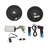
- Premium Materials: Crafted with high-strength aluminium alloy, rubber, and copper, it boasts exceptional corrosion endurance and structural integrity, ensuring dependable and stable performance over extended use.
- Strong Power: Equipped with two high-performance DC hub motors, each delivering up to 350W output power at a rated speed of 740rpm, it provides strong and consistent power output to easily tackle various riding challenges.
- Intelligent Adjustment: The throttle offers three-speed settings alongside forward/reverse motor control, enabling flexible adaptation to real-world conditions while balancing handling precision and energy efficiency.
- Convenient Reversing: An integrated reverse control button on the handlebar enables precise reversing use, ideal for situations demanding flexible steering like parking or turning around.
- Intelligent Protection: The controller's internal circuitry has excellent heat dissipation to prevent thermal overload. Its rugged interface cables ensure low failure rates during extended use, delivering a more secure riding experience.
Three lessons from that project are worth carrying into your own planning:
- Stock thickness can rule out a design. The OSB available to the author was too thin for a sturdy frame, even doubled, which led to a plywood-and-OSB sandwich. That was a result for one project, not a materials rule, and a plywood-and-OSB frame should not be assumed suitable for a powered vehicle that carries a rider.
- Subsystems can be defined separately. Splitting the machine into frame, bearing support, drive and tire lets each be designed and checked before integration.
- Cutting tools speed up iteration but do not supply engineering analysis. A waterjet or CNC router makes parts quickly; it does not show whether those parts will carry the loads.
Engineering questions to settle before building
A 2019 paper, “Design and fabrication of monowheel” by V. N. Loganathan, M. Karthick, C. Logeshwaran, S. Manoj Kumar and R. Mukesh, appeared in the International Journal of Intellectual Advancements and Research in Engineering Computations, volume 7, issue 2, pages 2875–2878 (DOI 10.61096/ijiarec.v7.iss2.2019.2875-2878). Its abstract names stress calculations, trusses, gyroscopic couple and circular geometry as core topics. The sequence below is planning guidance built from the design issues those records raise. It is not a tested procedure.
- Fix the architecture first. Decide how the inner frame is supported, how power reaches the outer wheel, how steering works and how the machine stays upright. Each choice constrains the others, so do not select a drive before the support concept is settled.
- Define the rider envelope and clearances. Model the rider’s seated or standing space against the rotating outer wheel through its full travel, including tire deflection, so that no moving part can reach the rider or the frame.
- Analyze the structure as load paths. Trace how rider weight, drive and braking forces, and impact loads move through the frame and bearings. This is where the stress calculations and truss-type load paths named in the 2019 abstract apply.
- Model gyroscopic effects. The 1994 patent relies on a flywheel for stability, and the 2019 abstract names gyroscopic couple as a topic. A spinning mass resists changes in its orientation and reacts to steering and lean inputs, so its effect has to be calculated rather than assumed to help.
- Design propulsion and braking as one system. Motor or engine, transmission, belt or chain, drive wheel and brakes must work together. Check each one for what happens when power is lost, a belt slips or a brake fails.
- Plan guarding, energy-source isolation and rider restraint. Define how exposed rotating parts are guarded, how batteries or fuel are isolated and protected, and how the rider is restrained.
- Fabricate to drawings and inspect against them. Produce engineering drawings with stated tolerances, check every part against them, and keep material certifications for critical members.
- Obtain qualified review, then controlled unoccupied testing. Have a structural or mechanical engineer review the loads and failure modes. Test without a rider, at low speed, in a controlled area, and consider rider tests only after those results are understood.
What the published record does not establish
These gaps are the reason this article stops short of a build sheet. The published material cited here does not provide:
- Overall dimensions, wheel diameter, frame geometry or clearances for any rider size.
- Material grades, load ratings or sizing for bearings, shafts, belts or pulleys.
- Motor, battery or engine ratings, or a method for sizing them.
- A validated control system or a validated braking design.
- A safe top speed, braking distance, stability margin or failure-mode analysis.
- Rider protection requirements or guarding guidance.
- Road-use rules. Vehicle and road regulations differ by jurisdiction, and the published record does not settle them for any region, so check local rules before riding on public roads.
The 2019 abstract does not supply dimensions, material grades, motor sizing or weld specifications, and the patents do not supply tested performance figures. Any build that goes beyond concept work needs those values established by an engineer for the specific design.
Quick wins for a faster PC:
Fix the driver behind crashes, sound loss and screen glitchesFind Drivers →Repair Windows errors before they cause bigger problemsFix Now →Scan for outdated or missing drivers - takes under a minuteDriver Scan →Quick Recap
Product prices and availability are accurate as of the date/time indicated and are subject to change. Any price and availability information displayed on Amazon at the time of purchase will apply.