Free tools Windows power users keep installed
One-click scans. No signup required.
AI is pushing advanced driver-assistance systems (ADAS) toward more powerful, integrated vehicle computing, but a faster AI chip is not by itself a safer car. ISO 26262 addresses hazards caused by malfunctioning electrical and electronic systems, while AI performance in difficult but fault-free conditions requires complementary analysis. Chiplets can help combine specialized processors and scale designs, but their interconnect, packaging, safety boundaries and production qualification all become part of the vehicle’s safety and reliability case.
How AI is changing ADAS computing
ADAS uses computation to interpret the driving environment and support functions such as driver assistance. As vehicles add AI-enabled functions, driver and passenger monitoring, and more connected in-vehicle systems, demand for compute rises. That pressure is one reason the industry is exploring more centralized and zonal vehicle architectures and higher-performance automotive systems-on-chip (SoCs).
Intel’s CES 2024 announcement described AI-enhanced automotive SoCs for in-vehicle applications including driver and passenger monitoring, alongside a commitment to an open UCIe-based chiplet platform for software-defined vehicles. This is evidence of a development direction, not proof that a particular architecture is deployed across production vehicles.
More compute can make room for additional functions, but it also concentrates responsibility: the vehicle program must show how the complete system responds to faults, how safety-related functions are separated or protected, and how the AI performs within its intended operating conditions.
Do these 3 things before closing this tab:
1Fix the driver behind crashes, sound loss and screen glitches2Clear out junk files and repair common Windows errors3Scan for outdated or missing drivers - takes under a minute#1 Best Overall
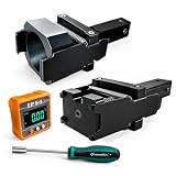
- 1.Dual Radar Compatibility: The Planar Radar Alignment Tool and Eyeball Radar Calibration Tool functions are combined in one setup, allowing professional technicians to work with both radar unit styles without switching to separate positioning fixtures.
- 2.ACC And Lane Assist Calibration: The Dynamic Angle Leveling Kit supports radar positioning during ACC dynamic calibration and Lane Assist Calibration Tool procedures, helping technicians establish the required sensor position during professional vehicle service.
- 3.Digital Angle Reference: The included digital inclinometer provides a clear numerical angle display while technicians adjust radar position and leveling. It helps reduce reliance on visual estimation during setup without adding unverified accuracy claims.
- 4.Controlled Radar Adjustment: The Radar Sensor Adjustment Tool setup combines the positioning fixture, digital inclinometer, and dedicated screwdriver so technicians can check angle changes and make controlled adjustments during calibration work.
- 5.Built For Professional Repair Bays: Durable metal construction supports repeated shop use, while the complete setup works as a Collision Repair ADAS Tool for body shops, independent repair facilities, and professional calibration specialists.
What ISO 26262 covers—and what it does not
Hardware development and random failures
ISO 26262-5:2018 sets out hardware-level product development requirements for road-vehicle applications. Its scope includes hardware safety requirements and design, evaluation of hardware architectural metrics, assessment of safety-goal violations caused by random hardware failures, and hardware integration and verification.
ISO 26262-11:2018 provides guidance on applying the ISO 26262 series to semiconductor development. It addresses hazards caused by malfunctioning safety-related electrical and electronic systems and offers possible interpretations of the standard for semiconductor work. In practice, the vehicle manufacturer and suppliers need safety evidence that connects semiconductor design and mechanisms to the allocated system-level requirements.
AI performance is a separate concern
ISO 26262 is not a score for perception accuracy and does not prove that a machine-learning model will handle every unusual scene. ISO 26262-5:2018 states: “This document does not address the nominal performance of E/E systems.” A system can operate without a hardware malfunction yet still produce an inadequate result because of limitations in its intended function or performance.
Rank #2

- Universal Compatibility: Fit for Honda, Toyota, Kia, and Ford vehicles,Whether you're a professional mechanic or a DIY enthusiast, this kit is designed to meet your ADAS calibration needs.Please confirm whether it meets your car model
- Calibration Kit: Enhance the safety and performance of your vehicle's advanced driver-assistance systems (ADAS) with this ADAS targeting reflector and stand kit, perfect for calibration tasks.
- The ADAS aiming corner reflector is a precisely engineered conical metal trihedron,that durable billet aluminum ensures that reflector maintains its shape and calibration accuracy over time. Type 18-8 stainless steel stand keeps stand stabilized on uneven surfaces.The ANGSO-AUTO ADAS calibration tool kit providing a reliable and consistent target for your vehicle's systems.
- Maximize ADAS Efficiency: The height-adjustment bracket features a clear scale from 0-30cm, enabling fast and precise adjustments. Say goodbye to time consuming guesswork and other tools helper . This tool reducing calibration time and improving the overall ADAS calibration experience.
- Easy Assembly: No special skills or complex tools required – just follow a few simple steps to set up the stand. It's designed with ease in mind, ensuring that even those with minimal DIY experience can assemble it with confidence and speed.
Vehicle programs therefore need to distinguish several assurance questions:
- Functional safety: how the system detects, controls or tolerates hazardous behavior caused by malfunctioning electrical or electronic components.
- Safety of the intended functionality (SOTIF): how risks arising from functional insufficiencies or performance limitations are identified and addressed, even when components are functioning as designed.
- Cybersecurity: how malicious access or manipulation is prevented, detected and managed.
- AI assurance: how the model and its data, operating conditions, limitations and updates are evaluated for the task it performs.
These are related but not interchangeable disciplines. A vehicle safety case must connect them where they affect one another, rather than treating ISO 26262 compliance as proof of AI correctness.
What chiplets are and why automotive designers are considering them
A chiplet architecture divides a larger computing system among multiple dies that are assembled in one package. Instead of building every function into a single monolithic SoC, a design can combine specialized dies—for example, CPU, AI, I/O, safety-related or memory functions—and reuse components across product variants.
Rank #3

- 1.Type:ADAS Calibration Tool for Planar Sensor Unit
- 2.Supported System :ADAS Calibration, ACC Calibration
- 3.Function:Allows technicians to easily adjust and align radar sensors for optimal performance. It provides accurate measurements and ensures that the radar sensors are placed at the correct positions, guaranteeing the reliability and effectiveness of the ADAS system
- 4.Easy to use:This angso-auto tool is highly user-friendly, making it suitable for both professional technicians and do-it-yourself enthusiasts
- 5.Durable and time-saving:It eliminates the guesswork associated with radar sensor positioning, saving your time and effort during the calibration process. Its durable construction ensures long-lasting performance, sturdy and durable,heavy-duty,making it a reliable addition to any workshop or garage.
That modularity can enable different manufacturing processes for different functions, shorten some redesign cycles, and reduce dependence on a single large die. It may also support scaling a compute platform across vehicle lines while allowing manufacturers to differentiate selected functions. These are architectural opportunities, not automatic cost or safety savings: the complete package and vehicle system still need to meet their requirements.
Monolithic SoCs, multi-chip modules and UCIe-style chiplets
A multi-chip module (MCM) places multiple dies in a package; the term alone does not establish a common interconnect, reusable ecosystem or safety strategy. UCIe is a defined die-to-die interconnect specification intended to support chiplet integration. The design’s actual implementation—not its label—determines how much reuse, portability and fault containment it achieves.
Recommended Free Tools
| Decision area | Monolithic SoC | Multi-chip module | UCIe-style chiplet system |
|---|---|---|---|
| Safety case and fault containment | Safety analysis focuses on functions and failure behavior within one die and its surrounding system; integration still requires system-level evidence. | Evidence must include interactions among dies and package-level effects; the MCM label does not define safety partitioning. | Evidence must cover each die, the interconnect, package and system; modularity does not itself establish safe fault containment. |
| AI throughput and latency | Compute and data movement are integrated on one die, but actual performance depends on the design. | Depends on the die arrangement and interconnect; no general throughput or latency value follows from the package type. | Depends on the selected dies, UCIe implementation and workload; no general performance figure follows from using UCIe. |
| Power and thermal behavior | Requires analysis of power and heat across the SoC and its vehicle installation. | Requires package-level thermal analysis across multiple dies. | Requires package-level thermal and mechanical reliability analysis across the chiplet assembly. |
| Test, traceability and qualification | Requires hardware verification and automotive qualification for the complete design. | Requires verification and traceability across the dies and their assembly. | Requires verification, traceability and qualification across dies, interconnect, package and suppliers. |
| Software and tools | Software and development tools are tied to the selected SoC and platform. | Integration depends on the dies and platform interfaces selected. | Standards can support interoperability, but software integration and tool portability still depend on implementations and vendor support. |
| Reuse, scale and supplier dependence | Reuse is centered on the SoC design and its variants. | Multiple dies may be combined, but reuse depends on the module design and interfaces. | Reusable dies and a standardized die-to-die interface may broaden configuration options; third-party supply and lifecycle support remain considerations. |
| Cost and supply resilience | Cost and supply exposure depend on the die, manufacturing process and sourcing strategy. | Multiple dies add integration and qualification work that must be balanced against design goals. | Reuse and alternative sourcing are potential benefits, not guaranteed savings; packaging, qualification and supplier coordination add work. |
What UCIe does—and what UCIe 1.1 adds
UCIe (Universal Chiplet Interconnect Express) is an open die-to-die interconnect specification covering the physical layer, protocol stack, software model and compliance testing. It is intended to standardize how dies communicate inside a package; it does not specify an entire automotive computer or replace system safety engineering.
Rank #4

- By utilizing the 180-degree scanning range of the servo motor, combined with the distance measurement capability of the ultrasonic sensor, for Arduino can detect targets and represent them on the screen with different colored dots.
- The TFT screen provides intuitive visual feedback, allowing users to understand the distance information of the targets.
- Distance Measurement: By using the ultrasonic sensor to measure the distance between objects and the sensor, it enables distance measurement and obstacle detection.
- Direction Sensing: By controlling the direction of the sensor through the servo motor, it allows obtaining the approximate directional position of objects in space.
- Real-time Monitoring: By continuously rotating the sensor and acquiring distance data, it enables real-time monitoring of the position and distance changes of objects.
The UCIe Consortium says version 1.1 retains backward compatibility with UCIe 1.0 and adds automotive-oriented capabilities including predictive failure analysis, runtime health monitoring and repair mechanisms. These features can contribute to monitoring and managing interconnect health, but they do not demonstrate that a given vehicle design detects every relevant failure or meets an automotive safety target. That requires evidence for the actual components, package, diagnostics, system response and use case.
Independent reader supportYour contribution helps us test, update, and keep practical guides available for everyone.Is automotive chiplet technology ready for cars?
There is concrete ecosystem activity, but public announcements and research programs are not evidence of universal production deployment. The dated milestones show investment in automotive chiplet development and qualification work:
- January 2024: Intel announced an open automotive UCIe chiplet platform and said it would work with imec on packaging quality and reliability for automotive use.
- August 5, 2024: Fraunhofer announced its Chiplet Center of Excellence, with its first two years focused on automotive electronics. Its planned work includes workflows, demonstrators, reliability evaluation, architectural concepts, reusable components and development roadmaps.
- October 10, 2024: imec announced its Automotive Chiplet Program. Initial committed participants included Arm, ASE, BMW Group, Bosch, Cadence Design Systems, Siemens, SiliconAuto, Synopsys, Tenstorrent and Valeo.
These initiatives address ecosystem development, interoperability, packaging and reliability. They do not establish that every UCIe version, chiplet combination or vehicle application is qualified for production. Samsung Foundry has also described automotive process offerings and development of UCIe die-to-die IP on 8 nm, 5 nm, 4 nm and 2 nm nodes; that is a vendor roadmap statement, not confirmation of a specific production program or design win.
What’s actually slowing this PC down?
Pick the symptom - the matching free tool is one click away.
What makes chiplets harder to qualify for automotive use
Splitting a design into dies changes the boundary of engineering and assurance work. The vehicle program must consider the package and interfaces along with the individual components.
- Package reliability: thermal cycling, mechanical stress and other package-level effects can affect a multi-die assembly over its intended service life.
- Interconnect behavior: die-to-die bandwidth and latency must suit the workload, while failures or degradation need appropriate detection and system response.
- Safety partitioning: designers need to show how faults in one die or interface are contained so they do not cause unsafe behavior elsewhere.
- Verification across suppliers: test coverage, traceability and safety evidence must be coordinated when dies come from different vendors.
- Software integration: interfaces and tools may differ across implementations; a standard does not make software automatically portable.
- Security: third-party dies and integration points add components and interfaces that need to be considered in the cybersecurity design.
- Lifecycle qualification: automotive programs have long development and qualification horizons, so component availability, revisions and support must fit the vehicle lifecycle.
How to decide whether a chiplet architecture fits an ADAS program
- Define the vehicle safety goals and operating domain. Specify what the ADAS function is expected to do and the conditions in which it is intended to operate.
- Allocate requirements across hardware and software. Identify which safety requirements belong to the SoC or chiplets, which belong to software and system controls, and what evidence each supplier must provide.
- Choose the partitioning approach. Compare a monolithic SoC, an MCM and a chiplet architecture against the workload, safety boundaries, reuse goals and expected vehicle variants.
- Select the interconnect and package. Evaluate bandwidth and latency needs, thermal and mechanical behavior, die-to-die diagnostics, repair strategy, security and automotive reliability evidence.
- Plan verification and operation. Define integration tests, fault injection, verification responsibilities and any field health monitoring needed for the selected design.
- Check production economics and lifecycle support. Weigh potential reuse and supplier flexibility against package engineering, qualification, software integration, sourcing and long-term support requirements.
The central trade-off is not simply “one chip versus several.” It is whether a modular architecture’s reuse and design flexibility justify the added package, integration and evidence burden for the specific ADAS function and vehicle program.
Quick Recap
Product prices and availability are accurate as of the date/time indicated and are subject to change. Any price and availability information displayed on Amazon at the time of purchase will apply.