An EV pre-charge circuit prevents a large, uncontrolled inrush of current when the traction battery is connected to the inverter and other high-voltage electronics. It charges the inverter’s DC-link capacitors through a controlled path before the main high-current contactor closes.
An EV pre-charge circuit prevents a large, uncontrolled inrush of current when the traction battery is connected to the inverter and other high-voltage electronics. It does this by charging the inverter’s DC-link capacitors through a resistor or controlled electronic circuit before the main high-current contactor closes.
As an Amazon Associate I earn from qualifying purchases.
Without pre-charge, those capacitors initially look almost like a short circuit. Closing a main contactor directly across an uncharged capacitor can create a violent current spike that causes arcing, contact pitting, welded contacts, fuse and cable stress, or damage to power-electronic components. Pre-charge does not make an EV battery safe to touch, but it is an important part of the vehicle’s high-voltage protection and switching system.
PC Slower Than It Used to Be?
A free scan shows the junk files, broken settings and background clutter dragging Windows down - then fixes them in one click.Free scan · Windows 10 & 11Crashes, No Sound, or Screen Glitches?
Random freezes, missing sound and display glitches usually trace back to one bad driver. Find and replace yours safely.Free scan · under a minuteWhat an EV pre-charge circuit does
The traction inverter, onboard charger, DC/DC converter, and related equipment commonly contain substantial DC-link or filter capacitance. The capacitor stores energy and smooths the battery’s DC supply for the inverter. When the vehicle is shut down, the capacitor is normally discharged or at a much lower voltage than the battery pack.
#1 Best Overall

- Connect any combination of solid, stranded, and flexible copper wires faster and more reliably
- Terminates 24-12 AWG for 221-41x, 20-12 AWG for 221-2401 solid
- Genuine WAGO LEVER NUTS
- Visually inspect for proper strip length and complete wire insertion through its transparent housing
- Includes: 8x 221-2401 (2 conductor inline), 8x 221-412 (2 conductor), 8x 221-413 (3 conductor), 4x 221-415 (5 conductor) with case
If a main contactor closes at that moment, the battery attempts to charge the capacitor as quickly as the wiring, contactor, battery, and capacitor will allow. The result is an inrush current that may be far higher than the normal operating current.
A pre-charge circuit adds a controlled impedance—traditionally a resistor—in series with a temporary charging path. The capacitor voltage rises gradually. Once the control system confirms that the DC link is close enough to battery voltage, the low-resistance main path is enabled and the pre-charge path is removed.
Typical EV pre-charge sequence
A conventional battery junction box or power distribution unit usually contains two main high-voltage contactors, a separate pre-charge contactor, and a pre-charge resistor. The simplified sequence is:
Do these 3 things before closing this tab:
1Fix the driver behind crashes, sound loss and screen glitches2Clear out junk files and repair common Windows errors3Scan for outdated or missing drivers - takes under a minute- Initial state: Both main contactors are open, and the inverter’s DC-link capacitor is discharged or below the required voltage.
- Start the charging path: The negative main contactor closes, followed by the pre-charge contactor. Current can now flow from the battery through the pre-charge resistor.
- Raise DC-link voltage: The resistor limits current while the inverter capacitor charges toward pack voltage.
- Verify the result: The battery-management or vehicle-control system compares DC-link voltage with battery voltage and checks whether the charging behavior is plausible.
- Transfer to the main path: The pre-charge contactor opens and the positive main contactor closes. The load is now supplied through the low-resistance main contactor rather than through the resistor.
The exact order, timing, voltage threshold, discharge strategy, and diagnostic logic vary by vehicle. Some systems close the negative contactor first; others use different switching arrangements. The principle remains the same: do not close the full-current path until the voltage difference across the main contactor is acceptably small.
Why closing a contactor without pre-charge is damaging
When the main contactor closes into an uncharged DC link, the initial current is limited mainly by battery and cable resistance, contact resistance, semiconductor resistance, and the capacitor’s instantaneous behavior. Those impedances can be very low.
The consequences can include:
- an arc across the contactor contacts as they approach or separate;
- contact pitting, erosion, or welding;
- stress on busbars, connectors, cables, and fuses;
- electromagnetic interference and voltage transients;
- damage to inverter input capacitors or switching devices; and
- a contactor that appears to operate but can no longer reliably interrupt the high-voltage circuit.
Pre-charge reduces the voltage difference across the main contactor before it closes. That greatly reduces the switching stress, but it does not eliminate every high-voltage hazard. Isolation monitoring, high-voltage interlocks, fusing, service disconnects, capacitor discharge provisions, and verified de-energization remain necessary.
The electrical principle: resistor, capacitor, and time
For a basic resistor-capacitor pre-charge circuit, the ideal capacitor voltage follows:
Recommended Free Tools
VC(t) = VBAT × (1 − e−t/RC)
Here, R is the effective series resistance, C is the total DC-link capacitance, and RC is the circuit’s time constant. The initial current is approximately:
Rank #2
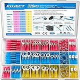
- Multiple Choices: Proper ratio of various types to meet the commonly used types needs. This wiring terminals kit contains ring, fork, spade, and heat shrink butt connectors
- Stronghold and Durability: We adopt premium copper core to ensure good electrical conductivity and durability. Heat shrink crimp connectors provides greater pull strength
- Waterproof: With the adhesive melted when heated, the heat shrink tubing seals all the way to the end of the barrel. The connections were to be outside or inside the vehicles, will perform good water proof
- Straightforward Visual Inspection: Translucent, adhesive-lined polyolefin tubing for straightforward visual inspection, prevents wire corrosion, and provides a waterproof seal
- Wide Applications: Good electrical conductivity and water proof provide connection for your automotive, motorcycle, and marine application. Widely used on multiple projects of your vehicle or ATV lighting, motorcycle stereo, boat electronics, equipment switches
IPEAK = VBAT / R
That estimate is idealized. Wiring resistance, contact resistance, semiconductor resistance, battery voltage behavior, and the actual load all affect the result.
| Elapsed time | Approximate capacitor voltage | Approximate remaining voltage difference |
|---|---|---|
| 1 time constant, 1RC | 63.2% of battery voltage | 36.8% |
| 2RC | 86.5% | 13.5% |
| 3RC | 95.0% | 5.0% |
| 5RC | 99.3% | 0.7% |
Designers must choose a pre-charge completion threshold based on the vehicle’s contactors, inverter, diagnostics, and operating requirements. A threshold somewhere around 90% to 98% is often discussed for this type of application, but it is not a universal EV specification.
Worked example
Texas Instruments gives an example involving an 800-volt battery, 1,000 microfarads of DC-link capacitance, and a 150-millisecond pre-charge requirement. Selecting roughly three time constants produces a resistance near 50 ohms and an initial current near 16 amps.
The example also illustrates why resistor selection is not simply a matter of choosing a part with the right resistance. At the beginning of the cycle, the resistor experiences substantial instantaneous power. The designer must check:
- maximum battery voltage, including charging and transient conditions;
- peak current;
- pulse energy;
- pulse duration and repetition rate;
- steady-state and average thermal limits;
- insulation, creepage, and clearance; and
- the effect of downstream loads that may operate during pre-charge.
The capacitor stores energy according to E = 1⁄2CV2. Because energy rises with the square of voltage, an 800-volt system places a much greater burden on the resistor and switching components than a lower-voltage system with the same capacitance. The 800-volt, 1,000-microfarad example is an illustration, not a general design rule.
Passive resistor pre-charge: simple, but not free
The conventional arrangement uses a resistor and a mechanical pre-charge relay or contactor. It remains popular because it is comparatively simple, has low control complexity, produces little switching noise, and uses widely available components.
Its disadvantages become more important as battery voltage, capacitance, and required startup speed increase:
What’s actually slowing this PC down?
Pick the symptom - the matching free tool is one click away.
- The resistor must tolerate high pulse power and repeated thermal cycling.
- Charging current decays as the capacitor voltage rises, so the process is not especially efficient.
- A large resistor or repeated startup cycles may require significant cooling.
- The pre-charge contactor must be correctly rated for the circuit’s voltage, current, switching conditions, and fault behavior.
- Unexpected inverter or converter loads can make the capacitor charge more slowly than expected.
A component marketed as an EV precharge resistor is not automatically suitable for a particular vehicle. A generic marketplace resistor or relay may lack the required pulse-energy, insulation, voltage, environmental, or fault-interruption rating. It should be treated as a search category, not as a universal replacement part.
Rank #3

- Solid Crimp: Thick tinned brass in every spade connector grips securely with low voltage drop and high current flow, helping prevent short circuits on each joint; Corrosion-resistant wire connectors deliver years of reliable service
- Nylon Insulation: Insulated sleeves guard against vibration and abrasion in engine bays or panel boxes; Quick disconnect terminals let you easily disconnect and reconnect wires without cutting or re-crimping
- Color-Coded Sizes: Red fits AWG 22-16, blue fits AWG 16-14, and yellow fits AWG 12-10, with male and female spade pairs in each range; Available in multiple sizes and pack options to fit different project needs, please confirm your wire gauge before ordering
- Versatile Use: Ideal for automotive wiring, speaker and stereo installations, trailer harnesses, and boat circuits where easy removal keeps maintenance simple; Female connectors pair securely with matching male terminals for fast, reliable connections whenever maintenance or replacement is needed
- Reliable Performance: Compliant with all electrical standards, whether you are working on your vehicle, home, or scientific project, these quick connector wire connectors help ensure secure and reliable connections
For perspective, TE Connectivity’s Mini K HV is described as an automotive pre-charge relay for systems up to approximately 450 VDC and pre-charge currents up to 20 amps when used with an appropriate resistor. Those are product-specific limits. They must not be generalized to an 800-volt pack or substituted for the requirements in a vehicle’s service documentation.
Active and solid-state pre-charge systems
Newer designs can regulate current electronically rather than allowing a fixed resistor to produce an exponentially declining current.
Solid-state switching
A solid-state relay can replace the mechanical pre-charge contactor. Texas Instruments’ TPSI3050-Q1 application material describes an isolated switch-driver approach that can drive external MOSFETs or IGBTs.
Quick wins for a faster PC:
Scan for outdated or missing drivers - takes under a minuteDriver Scan →Clear out junk files and repair common Windows errorsFree Scan →Potential advantages include faster switching, reduced mechanical wear, and a smaller package. However, the power semiconductors still require:
- adequate voltage and short-circuit ratings;
- controlled current during capacitor charging;
- thermal management;
- galvanic isolation where required;
- transient and overvoltage protection; and
- a defined fault-shutdown response.
Active current-controlled pre-charge
An active hysteretic buck-style circuit can regulate charging current with a MOSFET, inductor, current-sense components, comparator, and freewheel diode. Unlike a fixed resistor, it can maintain a more controlled current and potentially reduce charging losses and heat, allowing a smaller pre-charge assembly.
That efficiency comes with more design work. Switching frequency, comparator delay, semiconductor losses, inductor saturation, isolation, electromagnetic compatibility, and fault behavior all matter. Design calculators are useful starting points but do not necessarily include every delay or loss. Final component values should be checked through simulation and hardware testing.
TI’s TIDA-050063 reference design demonstrates an active-precharge architecture for up to 800 volts and up to 4 amps of average charging current with as much as 2 millifarads of load capacitance. It is a reference design, not a drop-in replacement for a production vehicle’s battery junction box.
Other design families include isolated switch drivers, active pre-charge controllers, discrete high-voltage buck converters, independent isolated DC/DC converters, bidirectional high-voltage-to-low-voltage DC/DC converters, and integrated pre-charge solutions. In general, advanced designs can improve power density or efficiency, but they add controls, isolation requirements, software considerations, component cost, and validation effort.
Rank #4

- 300PCS Wire Connectors Kit: 17 types of electrical connectors kit in the most commonly used sizes, which includes 2.8mm, 4.8mm, 6.3mm male and female spade connectors, fork connectors and ring terminals
- Insulated Crimp Connectors: Different colors correspond to different sizes in electrical wire connectors, 0.5-1.5 mm²/AWG 22-16 (Red), 1.5-2.5 mm²/AWG 16-14 (Blue), 2.5-6.0 mm²/AWG 12-10 (Yellow)
- Quality Materials: Spade connectors kit is made of tin-plated brass inserts and nylon sleeve to ensure that the terminals have excellent corrosion resistance and electrical conductivity while the nylon sleeve has good insulating properties
- Easy to Crimp: Strip the wire and place the crimp connectors in the crimping pliers, then crimp the end sleeve to secure the wire
- Wide Applications: Wire terminal connectors comply with electrical standards. Our electrical spade connectors, fork connectors and ring terminals set are suitable for auto, motorbike and household use, allowing you to connect wires without soldering in a short period of time
Pre-charge diagnostics: time alone is not enough
A robust controller should not declare success merely because a fixed delay has expired. It should measure the DC-link voltage against the battery voltage and evaluate whether the voltage rose in the expected way.
Useful diagnostic questions include:
- Did the DC-link voltage rise after the pre-charge path was commanded on?
- Did it reach the required fraction of battery voltage within the permitted time?
- Is the voltage difference small enough before the main positive contactor closes?
- Did the voltage rise too quickly, suggesting a bypassed or shorted resistor?
- Did the voltage remain low, suggesting an open resistor, open relay, wiring fault, or unexpected load?
- After the main contactor closed, did the voltage behave consistently with a low-resistance main path?
- After shutdown, did the DC link discharge as expected?
The exact thresholds and fault timers are vehicle-specific. A production controller may also use redundant voltage sensing, contactor feedback, welded-contactor checks, insulation monitoring, and interlock status.
Common pre-charge failure modes
| Failure | Likely electrical behavior | Why it matters |
|---|---|---|
| Open pre-charge path | DC-link voltage remains low or rises very slowly | Closing the main contactor could recreate the dangerous inrush |
| Open or thermally damaged resistor | Charging fails or becomes intermittent | The system may start only under some conditions or may time out |
| Shorted or bypassed resistor | Pre-charge current becomes much higher than intended | Contactor and capacitor stress can return |
| Pre-charge contactor welded closed | The resistor may remain connected to pack voltage | Continuous heating or loss of sequencing control may result |
| Main contactor welded | The high-voltage bus may stay energized after shutdown | This is a serious isolation and service-safety fault |
| Unexpected downstream load | Voltage rises slowly or fails to reach its target | The controller may diagnose a pre-charge fault even when the resistor is intact |
| Incorrect component rating | Breakdown, overheating, insulation failure, or contact damage | A part can appear electrically similar while being unsuitable for EV fault conditions |
How engineers select the hardware
Before choosing a resistor, relay, contactor, or active circuit, the design must establish the complete electrical envelope:
Free tools Windows power users keep installed
One-click scans. No signup required.
- Battery voltage: Include the maximum charging voltage, not only the nominal pack voltage.
- Total capacitance: Include the inverter, DC/DC converter, onboard charger, cable, and any other capacitive loads connected during pre-charge.
- Target time and voltage: Define how quickly the DC link must reach its acceptance threshold.
- Peak current: Calculate the initial current and check all tolerances and transients.
- Pulse energy: Verify the resistor’s single-pulse and repeated-pulse capability.
- Main contactor requirements: Check coil drive, contact resistance, continuous current, making and breaking capability, voltage rating, and welded-contact detection.
- Insulation and spacing: Verify isolation, creepage, clearance, enclosure, contamination, and environmental requirements.
- Fault behavior: Define what happens if the resistor, relay, sensor, controller, or main contactor fails.
- Service procedure: Confirm how the vehicle detects and discharges stored energy before authorized service work.
High-voltage contactors are not interchangeable simply because they share a current rating. Pre-charge contactors, main battery contactors, charging contactors, and auxiliary contactors may have different switching and fault requirements. TE Connectivity and Littelfuse both describe distinct automotive high-voltage contactor families and pre-charge applications; their ratings must be checked against the actual system design.
Pre-charge is not the whole EV safety system
Pre-charge controls capacitor inrush during startup. It does not protect a person from a live traction battery, guarantee galvanic isolation, interrupt every possible fault, or prove that the vehicle is de-energized.
A complete EV high-voltage safety design may also include:
- high-voltage fuses and current-limiting protection;
- service disconnects;
- high-voltage interlock loops;
- isolation monitoring;
- contactor feedback and welded-contactor diagnostics;
- controlled discharge of DC-link capacitors;
- touch-safe enclosures and insulated busbars; and
- documented lockout, verification, and repair procedures.
ISO 6469-3 addresses electrical safety for electrically propelled road vehicles, including voltage-class-B circuits, isolation-related protection, and testing provisions. The current authorized edition should be consulted together with applicable regional regulations, OEM requirements, component standards, and functional-safety processes.
What this means for EV owners and technicians
A failed pre-charge system can produce symptoms such as a vehicle that refuses to enter ready mode, a high-voltage system fault, contactor-related diagnostic codes, repeated startup timeouts, or a DC-link voltage that does not track battery voltage as expected. Those symptoms do not identify one failed part by themselves.
Best Value

- 【1-Second Connection - No Stripping】Still frustrated with soldering, stripping wires, or messy tape? These quick connect wire connectors solve it all. Just open the lever on our wire quick connectors, push the intact wire straight in, and snap it shut—secure connection in just 1 second. No stripping, no tools, no prep, ultra-simple for anyone.
- 【Premium Flame-Retardant Materials】 Crafted from high-quality PA66 flame-retardant nylon, this quick wire connectors ensures superior thermal stability. Stop worrying about melting or short circuits—even in high-temperature, demanding environments. The modified copper core guarantees optimal conductivity and corrosion resistance for a safe, reliable connection.
- 【Secure Locking - Never Pulls Out】 Innovative locking strip connector + independent clamp ensures wires stay locked firmly even with vibration. Ideal for LED strips, cars, and moving installations—say goodbye to loose connections!
- 【Reusable & Versatile for Any Wire】 Unlike one-time connectors, these double wire plug in connector fully reusable, allowing you to reconfigure wiring projects without wasting resources. Compatible with 22-18 AWG solid and stranded wires. The independent spring-clamp design adapts to various diameters, ensuring secure, stable electrical circuits.
- 【Wide Applications + Clean Wiring】Perfect for LED strip lights, speakers, fans, sockets, switches, motorcycles, cars, model kits, and all household low-voltage projects. The compact design fits easily into tight spaces, reducing wire clutter. Optimized for low-voltage, solderless fine wire connectors, it significantly speeds up projects for both professionals and DIY hobbyists.
Do not bypass the resistor, force a contactor closed, substitute a generic relay, or probe an energized traction-battery circuit based on an online diagram. High-voltage capacitors can remain charged after the battery contactors open, and a welded main contactor can leave parts of the vehicle energized when the normal shutdown sequence appears complete. Diagnosis and replacement should follow the vehicle manufacturer’s service procedure and be performed only by appropriately trained personnel with the required test equipment.
Where the hardware fits—and where it does not
For qualified designers, useful research categories include high-voltage EV pre-charge resistors, automotive HV pre-charge relays, main contactors, isolated switch drivers, and active-pre-charge reference designs. TI resources such as the TPSI31P1-Q1 and TPSI3052-Q1 families and the TIDA-050063 reference design are relevant starting points for active architectures. TE Connectivity’s Mini K HV and EVC/ECP families, along with Littelfuse DCN high-voltage DC contactors, illustrate the type of application-specific hardware used in EV and energy-storage systems.
Distributor catalogs from DigiKey and Mouser can help engineers compare contactors, pulse-rated resistors, isolated drivers, and evaluation boards, but catalog availability is not proof of vehicle suitability. Every candidate still needs verification of voltage, current, pulse energy, insulation, creepage and clearance, environmental rating, contactor breaking capability, coil requirements, and fault behavior.
For readers researching components rather than repairing a specific vehicle, an Amazon search for EV precharge resistor may surface related resistors, relays, kits, and electronics references. Marketplace listings should not be treated as approved production-vehicle parts unless their complete ratings and compatibility have been independently verified.
Frequently Asked Questions
What is pre-charge in an electric vehicle?
A pre-charge circuit charges the inverter’s DC-link capacitors through a resistor or controlled electronic path before the main high-voltage contactor closes. This limits inrush current and reduces arcing, contact welding, capacitor stress, and damage to connected power electronics.
How does EV pre-charge work?
A common sequence closes the negative main contactor and pre-charge contactor, monitors DC-link voltage as it rises, opens the pre-charge path, and then closes the positive main contactor. The exact sequence and voltage threshold vary by vehicle.
How do you calculate an EV pre-charge resistor?
The required resistance depends on battery voltage, total DC-link capacitance, desired charging time, and acceptable peak current. The resistor must also withstand the startup pulse energy and repeated thermal load; resistance alone is not enough to select a safe part.
The Tool Desk
Outbyte Driver Updater FREEScan for outdated or missing drivers - takes under a minuteDriver Scan →Outbyte PC Repair FREERepair Windows errors before they cause bigger problemsFix Now →What happens when an EV pre-charge circuit fails?
A failed pre-charge path can cause a high-voltage system fault, startup timeout, or DC-link voltage that remains too low. A shorted resistor, bypassed contactor, or welded main contactor can create more serious electrical and service-safety hazards.
Does pre-charge make an EV high-voltage system safe to work on?
No. Pre-charge reduces capacitor inrush during contactor operation, but it does not make the traction battery touch-safe or prove that the vehicle is de-energized. Isolation monitoring, interlocks, fuses, service disconnects, discharge circuits, and the manufacturer’s high-voltage service procedure are still required.
The Bottom Line
Pre-charge circuits make EV high-voltage switching safer by charging DC-link capacitors through a controlled path before the main contactor closes. The resistor, contactors, sensors, insulation, diagnostics, and discharge system must all be designed as one safety-critical system. A generic resistor or relay is not a safe substitute for the vehicle manufacturer’s specified hardware and service procedure.
Quick Recap
Product prices and availability are accurate as of the date/time indicated and are subject to change. Any price and availability information displayed on Amazon at the time of purchase will apply.