Do these 3 things before closing this tab:
1Fix the driver behind crashes, sound loss and screen glitches2Repair Windows errors before they cause bigger problems3Scan for outdated or missing drivers - takes under a minuteHardware-in-the-loop (HIL) testing connects a real electric-vehicle drive controller to a real-time computer model of the drive system. The controller sends its control signals to the simulated plant, which returns the signals the controller would receive from the motor and vehicle. Engineers can then test operating schedules, loads, and selected faults without using a high-power physical drive for every test. The result is only as trustworthy as the model, timing, interfaces, and test design; HIL complements physical validation rather than replacing it.
What HIL testing means for an EV drive
An EV-drive HIL rig puts real control hardware in a closed loop with a simulated plant. At minimum, it needs a device under test (DUT), a real-time plant model, and input/output interfaces that carry signals between them. A separate test-bench simulation can add vehicle dynamics, driving schedules, mechanical loads, and fault conditions.


The distinction is important: the controller is real, but the motor, inverter, vehicle, or some combination of them may be represented in software and real-time hardware. That lets engineers observe how the controller responds under controlled conditions without wiring it to a high-power physical traction drive for every test.
How the loop operates
- The real controller produces switching or control signals, such as commands for an inverter.
- Digital or analog I/O passes those signals into the real-time plant model.
- The model calculates the plant response and returns relevant feedback, such as voltage, current, or speed, to the controller.
- The test-bench simulation changes the operating point—for example, following a driving schedule or applying torque load—and can inject selected faults.
- Engineers record the controller and model response to assess whether the control behavior matches expectations.
Because the loop is closed and runs in real time, a controller interacts with the model as it would with a plant, rather than simply replaying a prerecorded trace.
The Tool Desk
Outbyte Driver Updater FREEScan for outdated or missing drivers - takes under a minuteDriver Scan →Outbyte PC Repair FREEClear out junk files and repair common Windows errorsFree Scan →#1 Best Overall
What an EV-drive HIL setup can represent
A 2012 IEEE paper by M. Kinsy and co-authors describes one specific implementation, not a universal recipe. Its three functional blocks were the DUT controller, a real-time electric-vehicle drive model, and a real-time test-bench simulation. The controller used scalar volts-per-hertz control with closed-loop motor-speed control and drove a six-pulse space-vector modulator. The demonstration used a 16 kHz switching frequency and 200 ns deadtime.
In that platform, an FPGA simulated a two-level, three-phase voltage-source inverter and an induction machine. The inverter model represented six IGBTs with antiparallel diodes. A separate test-bench simulation represented vehicle dynamics and generated mechanical torque loads and open-phase faults. These are the choices made in that experiment; other EV-drive tests may require different motor, inverter, vehicle, controller, or battery models.
Why timestep, latency, and model fidelity matter
Power-electronics controllers react to fast switching behavior. If a model step is too large, or signals arrive too late, the simulated response can diverge from the behavior the controller would encounter in the physical system. NI’s power-electronics guidance notes that increasing timestep raises simulated response error for PWM signals and says electric-motor models for HIL need to execute on the order of 1 μs. That is vendor guidance for this kind of application, not a universal threshold for every test.
| Figure | What it describes | Qualification |
|---|---|---|
| 1 μs fixed simulation step | FPGA-based EV-drive HIL platform in the 2012 IEEE paper by Kinsy et al. | A result from that implementation, not a general HIL specification. |
| Loop-back latency on the order of 1 μs | Same FPGA platform’s reported loop-back latency. | Platform-specific; actual requirements depend on the behavior being tested and the complete signal path. |
| Execution on the order of 1 μs | NI’s guidance for high-fidelity electric-motor simulation in HIL. | Vendor guidance, not an independently established requirement for all EV-drive models. |
Choose timing against the phenomenon under test: switching transitions, control-loop response, or slower vehicle-level behavior may impose different demands. Measure worst-case execution time and end-to-end loop latency on the configured system, and verify that I/O bandwidth, signal conditioning, and sampling behavior are suitable. A nominal timestep alone does not establish that the full loop is accurate or deterministic.
Model fidelity also needs evidence. Compare model outputs with physical measurements where feasible, and validate the model over the operating range relevant to the test. The 2012 paper compared its simulated drive with a small-scale physical EV drive under operating and fault conditions, including voltage, current, and speed measurements. Its results support that particular platform and comparison; they do not validate unrelated models or establish every real-world effect.
Tests HIL makes repeatable
HIL is useful when engineers need controlled, repeatable conditions or want to examine cases that are difficult, impractical, or potentially destructive to create on physical equipment. The 2012 demonstration used the EPA Urban Dynamometer Driving Schedule (UDDS), a light-duty-vehicle driving schedule, and included torque loading and open-phase fault cases.
Rank #3
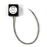
- Test loop troubleshooting tool to isolate whether the in ground loop or the detector is the problem
- Disconnect the in ground loop then connect TSTL leads to the detector loop inputs
- On most detectors connect red wire to input 7 and black wire to input 8
- Verify operation by passing a small metal object over the TSTL test area to trigger detection
- Two wire red black design compact size 1.25 x 1.25 x 0.75 in compatible with most loop detectors
A practical test sequence
- Validate the plant model. Check its response against known behavior or physical measurements for the relevant operating range.
- Run representative operating cycles. Apply the driving schedule and loads needed to exercise the controller’s expected operating conditions.
- Introduce controlled faults. Use defined fault-insertion methods, such as the open-phase case in the cited demonstration, and confirm that the injected condition reaches the intended part of the loop.
- Inspect controller behavior. Log the relevant control signals and simulated or measured quantities, then assess response against the test criteria.
- Correlate where possible. Compare HIL results with physical-system measurements to identify model or interface differences.
These tests can expose controller behavior across repeatable conditions, but a simulated fault is not automatically equivalent to a physical fault. The model, fault-insertion path, I/O, and test criteria all affect what the result demonstrates.
Signal-level HIL and power-level testing answer different questions
Signal-level HIL connects a controller to simulated electrical and vehicle behavior through signal I/O. It is suited to testing software and electrical functionality at the signal level without running a high-power traction system. Power-level or dynamometer testing brings additional power hardware into the setup and can address questions that a signal-only loop cannot answer.
Crashes, No Sound, or Screen Glitches?
Random freezes, missing sound and display glitches usually trace back to one bad driver. Find and replace yours safely.Free scan · under a minutePC Slower Than It Used to Be?
A free scan shows the junk files, broken settings and background clutter dragging Windows down - then fixes them in one click.Free scan · Windows 10 & 11NI describes a workflow that can expand from signal-level inverter-controller tests toward power-level or eDyno testing, with models and test assets reused where appropriate. Moving between levels may require expanded I/O and integration of third-party power-electronics hardware; reuse does not mean the two setups provide interchangeable evidence. NI also describes use of simulated vehicle dynamics, battery, and electromechanical models on FPGAs, plus communications, fault insertion, and multi-ECU workflows. These are vendor-described capabilities to evaluate, not a neutral comparison of suppliers.
NI’s Electric Drive Test page reports a Subaru Electric Motor ECU HIL customer-story result of test time reduced to 1/20 of the estimated time for equivalent dynamometer testing. This is NI’s reported customer-story claim for that case, not a general productivity expectation for HIL programs.
Independent reader supportYour contribution helps us test, update, and keep practical guides available for everyone.How to evaluate an EV-drive HIL platform
Start with the DUT and the behavior the test must establish, then compare platforms against the required loop and test workflow. There is no independent cross-vendor benchmark in the sources cited here, so feature lists should not be mistaken for comparative performance evidence.
- Real-time performance: Confirm timestep, worst-case execution time, loop latency, and model fidelity for the switching or control phenomena in scope.
- I/O fit: Check analog, digital, PWM, encoder, and communications interfaces, along with voltage range, bandwidth, isolation, signal conditioning, and fault-insertion needs.
- Model integration: Establish whether existing vehicle, battery, motor, and inverter models can be used, including tools such as Simulink where relevant.
- Test operations: Assess deterministic logging, automation, repeatability, multi-ECU support, and CI/CD integration if required by the program.
- Scaling path: Determine whether the system can expand from signal-level controller tests to power-level or dynamometer work, and what additional equipment that entails.
- Lifecycle and ownership: Consider model portability, ownership, vendor dependence, maintainability, technical support, and total system cost.
For any candidate system, verify performance with the intended model, interfaces, and DUT configuration. Published platform capabilities can help identify questions to ask, but only a test configuration that meets the project’s requirements can establish suitability.
Standards: HIL practice versus EV component tests
Standards mentioned in this area address different scopes. IEEE 2004-2025 is the closest of these sources to HIL method guidance, while ISO 21782-3 and ISO 21782-6 specify motor-and-inverter component test procedures rather than HIL architecture.
| Standard | Scope stated by the publisher | What it is not |
|---|---|---|
| IEEE 2004-2025 | IEEE recommended practice for real-time HIL simulation-based testing of electric power apparatus and controls. IEEE lists its publication date as 2025-08-29 and describes recommendations for setup and execution, analytical frameworks for stability, accuracy, and sensitivity assessment, and experimental case studies. | Not an EV motor/inverter component test specification. |
| ISO 21782-3:2019 | Performance tests for the motor and inverter of a voltage-class-B electric propulsion system for electrically propelled road vehicles. ISO lists the standard as at a stage marked “International Standard to be revised.” | Not a HIL architecture standard; check lifecycle status before applying or purchasing it. |
| ISO 21782-6:2019 | Operating-load tests and criteria for the motor and inverter of a voltage-class-B electric propulsion system. | Not a HIL architecture standard. |
The standards’ scopes do not establish that compliance with any one of them is legally required for a particular vehicle or market. Applicability depends on the relevant program and jurisdiction.
Quick Recap
Product prices and availability are accurate as of the date/time indicated and are subject to change. Any price and availability information displayed on Amazon at the time of purchase will apply.