To stop automotive electronic noise, first determine how it reaches the affected circuit: through power or signal wiring, by radiation, or by magnetic coupling. Then correct return-current paths and bonding before adding a filter or shield. A part that works on one path may do little on another, and component-level improvement does not establish vehicle-level electromagnetic compatibility.
How do you tell whether noise is conducted, radiated or magnetically coupled?
Reproduce the symptom and change one likely source at a time. Try different engine speeds and alternator loads, and note whether the noise changes when motors, relays, inverters or communications transmitters operate. A change that tracks engine speed is a useful clue, not proof that the noise is conducted: the source may couple into a signal or harness through more than one path.
For an audio complaint such as alternator whine, compare conditions such as engine off versus running, different engine speeds, and different audio inputs or operating states. Record what changes and what does not. Avoid disconnecting the battery while the engine is running; use appropriate diagnostic procedures for the vehicle.
| Possible path | Clues to investigate | What to examine |
|---|---|---|
| Conducted through power or signal wiring | The disturbance appears in a circuit connected to the suspected source, or changes when its electrical load changes. | Supply and return wiring, connector returns, grounding, and whether the affected circuit shares a current path with the source. |
| Radiated coupling | The symptom responds to transmitter activity, harness or component placement, or proximity to a likely RF source. | Harness routing, enclosure seams, shield coverage, and termination at connectors and enclosures. |
| Magnetic coupling | The symptom changes with the relative placement or orientation of a source and a susceptible loop or harness. | Loop area, separation, routing, and whether supply and return conductors run together. |
These clues help select a test; none identifies the path conclusively by itself. A current probe can help examine current on a conductor, while near-field probes, an oscilloscope and a spectrum analyzer can help locate or characterize disturbances. Use suitable probes and measurement setups for the frequency and circuit involved.
#1 Best Overall

- Locate Open & Short Circuits Fast – Automotive wire tracer helps identify open wires, short circuits, and circuit paths with transmitter signal and audible receiver feedback for faster troubleshooting
- Trace Hidden Wiring – Cable tracker follows wires behind panels, under carpets, through harnesses, and in accessible low voltage areas without cutting or damaging insulation
- 6-42V DC Electrical Tester – Designed for automotive electrical systems, car repairs, trailers, trucks, and other low voltage DC circuit diagnostics
- 7 Inch Flexible Probe – Bendable probe reaches tight spaces around dashboards, fuse boxes, connectors, and wire harnesses for easier circuit tracing and signal detection
- Non-Contact & Easy to Use – Circuit tracer and voltage detector setup helps locate wiring issues without piercing wires, making it useful for automotive and low voltage diagnostic work
What should you correct before installing a filter?
Inspect the complete current-return path, not just the ground connection at the device. A loose or poor bond, connector return, or shared path can let unwanted current create a voltage difference where a sensitive circuit interprets it as a signal. Check relevant ground straps, connector contacts and shield bonds, and compare the installation with the vehicle and component manufacturers’ requirements.
Keep analogue, digital and power sections appropriately separated, with a grounding strategy that does not make sensitive signal returns carry unrelated load current. Com-Power’s application note recommends separating these sections with careful grounding. Physical separation and routing should also limit unnecessary coupling between noisy power conductors and susceptible signal wiring.
Rank #2

- 【PRECISE READOUTS & CLEAR DIGITAL DISPLAY】Bright LED display shows highly clear readings in any lighting condition, 0.1V resolution gives you reliable indication and shows you the voltage number easily & quickly. Bidirectional light emitting diode on the circuit board for easy battery load testing, red light indicates positive polarity, green light indicates negative polarity.
- 【QUICK DETECTION & EXTENSIVE USE】WINAMOO auto circuit tester helps you to quickly test car battery voltage and diagnoses issues in 3V-48V systems, including alternator tester functionality of car/truck/SUV/boat charging systems. Also to inspect circuit tester integrity of headlights, taillights, turn signal circuits, faulty sockets, fuse connections and more.
- 【SHARP PROBE & ANTI-LOST PROTECTIVE SLEEVE】Sharp stainless steel probe for piercing insulation with ease, also for hard to reach tight areas. Integrated anti-lost protective sleeve to secure the probe during storage and safeguarding against damage, making sure no stab and wound and won't be lost wherever you go.
- 【EXTENDED SPRING WIRE & LARGE ALLIGATOR CLIP】High quality 96 inch long enough spring wire increases flexibility to access across broad areas when testing. Attaching with large crocodile clip for easy single-handed operation, which is boosting the efficiency for car battery capacity checks and beyond.
- 【ULTRA-DURABLE & SAFE CONSTRUCTION】This voltage tester pen adopts ergonomic handle for comfort and safe grip. Constructed with premium ABS body with higher transparency, shatter-proof and durable. Ensuring reliable battery meter and circuit analysis for safe operation, making them an essential tool in electrical troubleshooting.
- Look for damaged, loose or corroded connections and unintended shared returns.
- Check that supply and return conductors follow the intended path together where appropriate, rather than creating a large loop.
- Review harness routing and the intended bonding arrangement before changing shield connections.
- Make one change at a time and repeat the same operating conditions so the effect is interpretable.
Do not assume that adding a wire from a shield to chassis will improve the result. Shield bonding depends on the equipment, harness, frequency and installation. Follow the component or vehicle design requirements and verify the complete assembly.
When is an automotive EMI noise filter appropriate?
Consider a power-input filter when evidence points to noise entering through the supply wiring. An LC or pi filter can reduce conducted interference in a suitable circuit, but its presence alone is not evidence that it will solve a particular complaint. Selection must account for insertion loss across the relevant frequencies, allowable current and voltage, high-frequency parasitics, and the way the filter interacts with the source and load.
Do these 3 things before closing this tab:
1Repair Windows errors before they cause bigger problems2Fix the driver behind crashes, sound loss and screen glitches3Clear out junk files and repair common Windows errorsRank #3

- 🥇【2026 ALL-IN-ONE POWER CIRCUIT TESTER KIT---ACCURATELY】If device is not working properly and requires repair, please cont.act:📞autelsupply@ outlook. com📞 get support. Autel Circuit Tester is most accurate power circuit probe tester yet, test all 6-30 volt vehicle electrical systems. It supports ✅Voltage&Polarity Test✅Continuity Test✅Signal Circuit Test✅Components Activate✅Check Bad Grounding✅Locate Short Circuits✅Circuit Breaker Protection, etc. Also, Autel Power Circuit Tester has long Cables (itself 20ft & extra 20ft cable), comes with a cigarett.e lighter plug. Intuitive interface with ergonomic design makes it be best gif.t for all novice drivers or pro circuit repairers.
- 🥇【ADVANCED FOUR WORKING MODE---INTUITIVE&EASY】Four working modes make circuit detection more simple. DC Voltage, AC Voltage, Resistance, Tone On/ Off. 1) DC Voltage mode can read DC voltage with 0.1V resolution. 2) AC Voltage can get Min & Max voltage, duty cycle and frequency quickly. 3) Resistance mode to read resistance between tip and auxiliary ground wire. 4) Unique Tone On/ Off Design is really useful when working in dim areas, it can judge the circuit voltage according to the volume of the sound. Note: Any issues please reach out to us via: 📞autelsupply@ outlook. com📞.
- 🥇【COMPONENT ACTIVATION & TEST】This Autel automotive power circuit probe tester can activate components on/off-board electrical system/ equipment, is designed for car technician or car enthusiasts. By activating the signal generated by the component, you can accurately judged whether the component is intact, such as blower motor, power window motor, windshield wiper, rear window defroster, lights, radiator fans, fuel injectors, etc. Autel circuit tester automotive tool can activate component in your hand/ in the vehicle/ with ground etc.
- 🥇【INSTANT IDENTIFY POLARITY】Autel Car Circuit Tester instantly checks component continuity and quick identifies positive, negative and open circuits. When the positive terminal is connected, red LED lights up with beep sounds. When the negative terminal is connected, green LED light up with a low tone. If an open circuit, neither of LED light will not light. The indicator light is a considerate working guide to facilitate the smooth operation of detection. If device is not working properly, please cont.act:📞autelsupply@ outlook. com🛣️ get support.
- 🥇【CONTINUITY TEST, SIGNAL CIRCUIT TEST】Autel Electrical System Probe Tester can test the state of sensors, quickly and accurately judge the connectivity of circuit via transmit signal, performing continuity test. Two ways to test continuity: ✅1: In resistance mode, if the resistance is 0.0Ω and the LED lights up, it means continuity. ✅2: Power up the connection using the power switch, if the circuit brea-ker tr-ips, that means the resistance is low and there is continuity.
- Insertion loss: Check performance over the frequencies that matter; a nominal rating at one frequency does not establish attenuation across the full problem range.
- Voltage and current: Confirm continuous and transient electrical ratings suit the vehicle circuit and load.
- Resistance and heat: Account for voltage drop, DC resistance and heat under the actual load.
- Parasitics: Inductance and capacitance can affect behavior at high frequencies and may alter the circuit response.
- Installation: Check connector, harness and grounding geometry. Poor layout can undermine the intended filter performance.
- Environment and evidence: Confirm environmental suitability and look for relevant standardized test evidence rather than relying only on a component description.
Choose an automotive EMI noise filter only after confirming compatibility with the circuit’s voltage, current, connector and relevant frequency range. If the path is radiated or magnetic, a power filter may not address it; correct routing, bonding, separation or shielding may be more relevant.
How should cable shields and enclosures be terminated?
For RF or high-speed coupling, continuous braided or foil shielding can reduce electromagnetic energy entering or leaving a harness or enclosure. The shield’s coverage matters, but so does the termination: a discontinuous shield or a poor, high-impedance connection can compromise the intended protection. TE describes shielding as a way to prevent electromagnetic radiation from entering or leaving an area and to protect components inside enclosures.
Rank #4
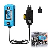
- 【High-Precision Current Measurement for Quick Fault Diagnosis】 Expertly designed for high-accuracy electrical current measurements of household and commercial vehicles, this tester delivers real-time readings and detects even minute current fluctuations. It enables both novices and professionals to quickly and accurately identify circuit faults, effectively resolving automotive electrical issues without complicated operations
- 【Clear Data Reading & Efficient Low-Light Operation】 Equipped with a blue back lit LCD screen, current data can be clearly read in both strong and low light conditions, ensuring no subtle current fluctuations are missed. The built-in front light illuminates the work area during nighttime maintenance, enhancing operation safety and efficiency, and allows you to complete professional-grade circuit tests even in dark environments
- 【Versatile Application & Portable Compact Design】 Suitable for various circuit testing needs of passenger cars and commercial trucks, this tester handles everything from minor family car troubleshooting to complex commercial vehicle circuit tests. Its lightweight and compact design ensures easy carrying and storage, making it ideal for mobile diagnostics, busy workshops, or outdoor maintenance scenarios
- 【User-Friendly & Durable Construction for Long-Term Use】 Made of non-slip ABS/PC material with an outer rubber coating, the tester offers a comfortable and secure grip, reducing fatigue during extended use. It features robust impact resistance and waterproof performance, which can withstand the rigorous demands of automotive environments and ensure long-lasting reliability for daily work
- 【Simple Operation & Long Battery Life】 The tester has no complicated learning curve—just remove the blade fuse, insert the tester’s safety into the wire socket, and plug it into the vehicle fuse socket (max load 20A/48V) to start testing. It supports long-lasting battery power, allowing for multiple continuous tests on a single battery and eliminating the need for frequent battery replacements
Use the shield construction and termination specified for the harness or equipment, maintaining continuity through connectors and enclosure interfaces where the design requires it. Prefer a broad, low-impedance bond appropriate to the design over an improvised long drain-wire connection for an RF termination. Whether the shield should bond at one end, both ends, or by another arrangement is installation-dependent; do not apply a universal rule in place of the manufacturer’s bonding scheme.
When assessing a shielding fix, consider frequency range, shielding effectiveness, harness and connector geometry, bonding method, enclosure seams, and environmental rating. A strip of shielding tape or a conductive gasket cannot compensate automatically for a poor connector transition or interrupted shield path.
Quick wins for a faster PC:
Clear out junk files and repair common Windows errorsFree Scan →Fix the driver behind crashes, sound loss and screen glitchesFind Drivers →Repair Windows errors before they cause bigger problemsFix Now →Best Value

- SEE & HEAR THE SIGNAL — AUTOMOTIVE WIRE TRACER WITH LED BARS & AUDIBLE TONE — This automotive wire tracer gives both visual and audible signal feedback while tracing vehicle wiring. When the transmitter indicates an OPEN condition, the receiver responds with green OPEN LED bars; when it indicates a SHORT condition, the receiver responds with red SHORT LED bars. As the probe gets closer to a signal-carrying wire, the beeping becomes louder, and the LED bar rises, helping you follow signal changes with two clear indicators instead of relying on sound alone.
- TRACE OPEN CIRCUITS, BROKEN WIRES & POOR CONNECTIONS — Use this broken wire detector and open circuit finder to follow a circuit from the transmitter toward the load. While it detects a signal, the receiver beeps and shows green LED-bar feedback. If the sound and green LED bars diminish or disappear, the probe may be moving away from the wire or may have passed an open circuit, wire break, or poor connection. Check both sides of the suspected location to verify the signal change.
- LOCATE SHORT CIRCUITS — SHORT CIRCUIT FINDER WITH RED LED FEEDBACK — Connect the transmitter in series with the circuit as instructed, then move the receiver along the wire from the transmitter toward the load. While the signal is detected, the receiver provides beeping and red LED bar feedback. A significant change or disappearance of the red signal can indicate the suspected short-circuit area. Reposition the probe around that location and compare the signal on both sides to help verify the fault area.
- 3-LEVEL SENSITIVITY + BENDABLE FAULT PROBE — The receiver offers three selectable sensitivity ranges: Level 1 Low, Level 2 Medium, and Level 3 High, allowing you to choose a range based on the circuit and detection conditions. If the receiver has difficulty detecting a signal, the instructions recommend switching to Level 3 and checking again. The coiled-steel probe can also be bent to access crowded or hard-to-reach wiring areas. For the recommended detection position, keep the probe tip close to the wire and approximately 90° to the wire being traced.
- CONTINUITY TESTER FOR DC VEHICLE CIRCUITS UP TO 42V — The transmitter also includes a CONT mode for checking wire continuity. Attach the two clips to both ends of the wire being tested; a green light indicates continuity, while no green light indicates a wire fault. This electrical circuit tester is designed for DC circuits only and must never be connected to circuits exceeding 42V DC or to AC power. Do not use it on ignition-system components, and inspect or disconnect voltage- or current-sensitive vehicle systems as directed by the vehicle service manual before testing.
Which automotive EMC standards apply?
The appropriate standard depends on what is being tested. CISPR 25 addresses radio disturbance from vehicle components or modules as it relates to protecting on-board radio receivers. ISO 11452 provides component immunity test methods. CISPR 25 is not a general test for protecting electronic control systems from RF emissions or transient and pulse voltage fluctuations.
| Standard and edition | What it addresses | Scope detail |
|---|---|---|
| CISPR 25:2021 | Radio disturbance limits and measurement procedures for automotive components and modules, with the aim of protecting on-board receivers. | 150 kHz to 5,925 MHz. IEC states the limits are intended to protect on-board receivers installed according to the manufacturer’s guidelines from disturbances produced by components or modules in the same vehicle. Published 2021-12-16. |
| ISO 11452-1:2025 | General principles for component immunity testing. | Permitted test range spans DC and 15 Hz to 18 GHz. Published June 2025. |
| ISO 11452-2:2019 | Component immunity using an absorber-lined shielded enclosure. | Use when this method fits the immunity question and applicable test plan. |
| ISO 11452-4:2020 | Harness excitation for component immunity. | Includes bulk current injection and tubular-wave-coupler methods. |
| ISO 11452-10:2009 | Conducted disturbance testing in the extended audio-frequency range. | Remained current after its 2026 review. |
Use the applicable edition and method for the component, vehicle program and test objective. CISPR 25 emissions results do not by themselves demonstrate immunity, and an ISO 11452 immunity test does not replace an emissions test. For electronic control-system RF emissions or transient and pulse-voltage topics outside CISPR 25’s stated coverage, identify the relevant ISO publication and test requirements rather than treating CISPR 25 as a universal EMC standard.
How do you verify that a fix worked?
- Define repeatable conditions: Record the operating state, engine speed or load condition, active equipment and symptom before changing the installation.
- Identify the likely path: Use the observed changes and appropriate measurement tools to distinguish a wiring path from radiated or magnetic coupling.
- Make a targeted correction: Repair a return or bond, change routing or separation, install a suitable filter, or improve shield continuity according to the identified path.
- Repeat the original checks: Test under the same conditions and confirm whether the symptom and measured disturbance changed.
- Validate the complete installation: Where compliance or robust vehicle integration is required, test the component and its installed configuration using the relevant CISPR 25 emissions and ISO 11452 immunity setup.
A component’s standalone performance does not prove vehicle-level compatibility. Harness length and routing, connector interfaces, bonding, enclosure details and operating conditions all affect the installed result.
Quick Recap
Product prices and availability are accurate as of the date/time indicated and are subject to change. Any price and availability information displayed on Amazon at the time of purchase will apply.