Yes—an ESP32 can capture CAN bus traffic and forward it wirelessly over Wi-Fi or Bluetooth. The important qualification is that the ESP32 is not, by itself, a complete CAN interface. Its built-in CAN-compatible controller is called TWAI in Espressif documentation, and it requires an external CAN physical-layer transceiver connected between the ESP32’s logic pins and the vehicle’s CANH/CANL wires.
For a safe passive monitor, configure TWAI in listen-only mode. The ESP32 can then receive Classical CAN frames without intentionally transmitting data, acknowledgements, or error frames onto the vehicle network. This makes it suitable for logging, live dashboards, and wireless analysis—but not automatically for controlling a vehicle or decoding signals such as RPM and vehicle speed.
As an Amazon Associate I earn from qualifying purchases.
What the ESP32 wireless CAN reader actually does
The project has four separate parts:
- CAN bus: the vehicle or equipment network carrying differential CANH and CANL signals.
- CAN transceiver: converts the differential bus signals into logic-level TX and RX signals.
- ESP32 TWAI controller: receives, filters, timestamps, and checks CAN frames.
- Wireless transport: sends captured frames to a phone, laptop, local dashboard, or server.
Vehicle CANH/CANL
        |
        v
External CAN transceiver
  CANH/CANL <-> TXD/RXD
        |
        v
ESP32 TWAI controller
        |
        +-- Wi-Fi: TCP, UDP, WebSocket, HTTP, MQTT
        +-- Bluetooth: BLE GATT or Bluetooth Classic SPP
The ESP32 handles the CAN protocol mechanics—arbitration, frame formatting, identifier filtering, reception, and error handling. The transceiver handles the electrical layer. Wi-Fi or Bluetooth does not replace either part.
Required hardware
| Part | Purpose | What to verify |
|---|---|---|
| ESP32 development board | TWAI controller and wireless radio | Chip family, exposed GPIOs, supply voltage, and Bluetooth capability |
| 3.3-V CAN transceiver module | Electrical connection to CANH and CANL | Logic voltage, CAN speed, pinout, Classical CAN support, and termination |
| CAN wiring or connector harness | Connects the transceiver to the target bus | CANH/CANL polarity, ground/reference, connector pinout, and strain relief |
| Suitable power supply | Powers the ESP32 and transceiver | Regulation, protection, current capacity, and vehicle-voltage compatibility |
| 120-ohm CAN termination resistor | Terminates a bench bus or physical endpoint when required | Never add it merely because the reader is present |
The ESP32 board must not be connected directly to vehicle battery voltage. Automotive electrical systems can produce voltage transients well above their nominal battery voltage, so a vehicle installation needs an appropriate protected power supply or automotive-rated adapter.
#1 Best Overall

- 2.4GHz Dual Mode WiFi + Bluetooth Development Board
- Support LWIP protocol, Freertos
- SupportThree Modes: AP, STA, and AP+STA
- Ultra-Low power consumption, Compatible with Arduino IDE
- ESP32 is a safe, reliable, and scalable to a variety of applications
Choosing the ESP32 board
The original ESP32-WROOM-32 combines 2.4-GHz Wi-Fi, Bluetooth Classic, Bluetooth LE, and a TWAI controller compatible with Classical CAN Specification 2.0. It remains useful for experiments and existing designs, but Espressif marks the ESP32-WROOM-32 as Not Recommended For New Designs. For a new product, select a currently supported ESP32 family member and check its exact peripheral and radio capabilities.
Do not assume that every newer ESP32 has Bluetooth Classic. The original ESP32 supports Bluetooth Classic and BLE, while several newer families support BLE but not Bluetooth Classic. Choose according to the host device:
- Wi-Fi: best for streaming to a laptop, local web dashboard, network service, or MQTT broker. The ESP32 can operate as a station joining an existing network or as a SoftAP creating a local network.
- Bluetooth Classic SPP: convenient when the receiving software expects a wireless serial port. This is particularly relevant to the original ESP32.
- Bluetooth LE GATT: better for modern phone applications and low-power, intermittent data exchange. A notify characteristic can carry captured frames while a write characteristic accepts configuration.
Choosing the CAN transceiver
A suitable transceiver must match the ESP32’s logic voltage and the target CAN physical layer. A device such as the 3.3-V SN65HVD230 family is a relevant example: its specified supply range is 3.0–3.6 V, it is intended for ISO 11898-2 networks, and it supports CAN rates up to 1 Mbps. Other transceivers, including TJA105x-family devices, may also be appropriate, but their supply and logic-level requirements must be checked individually.
A breakout board can simplify the build by providing a connector, power pins, and sometimes switchable 120-ohm termination. It is still necessary to read the board schematic. Board labels such as TX and RX can be ambiguous: some identify signals from the microcontroller’s perspective, while others identify the transceiver’s perspective.
Wiring the ESP32 to the CAN bus
A typical connection looks like this:
| ESP32/TWAI signal | Transceiver pin |
|---|---|
| TWAI TX GPIO | TXD or driver-input pin |
| TWAI RX GPIO | RXD or receiver-output pin |
| 3.3 V, if required | VCC or VIO according to the transceiver datasheet |
| GND | GND/reference |
| — | CANH to bus CANH |
| — | CANL to bus CANL |
Use GPIOs that are actually available on the selected board and configure those same pins in the TWAI driver. The names and routing options vary by board. Confirm the connection from the board schematic and transceiver datasheet rather than relying on a generic ESP32 pin diagram.
CAN termination: the common wiring mistake
A normal high-speed CAN network has approximately 120-ohm termination at each physical end of the bus. Those resistors are properties of the complete network, not automatic requirements for every node.
- A reader attached in the middle of an existing vehicle bus generally should not add another termination resistor.
- A two-node bench network normally needs termination at both ends.
- A reader that physically becomes a bus endpoint may need termination, depending on the network design.
Adding a third 120-ohm resistor to a correctly terminated vehicle network can load the bus and cause communication problems. If a breakout has switchable termination, leave it disabled unless the reader is intentionally at a physical endpoint.
Do these 3 things before closing this tab:
1Clear out junk files and repair common Windows errors2Scan for outdated or missing drivers - takes under a minute3Repair Windows errors before they cause bigger problemsConfigure TWAI for passive capture
For a monitor, the central design decision is listen-only mode. In this mode the controller observes the bus without transmitting dominant bits, acknowledgements, or error frames. That reduces the chance that the reader changes the behavior of the network.
Listen-only mode is safer than ordinary receive mode for a passive monitor, but it does not make an unsafe installation harmless. Incorrect wiring, electrical faults, a mistaken firmware configuration, or another active interface can still affect a vehicle network. Keep the design physically and logically incapable of transmission wherever practical.
Typical firmware sequence
- Select the TWAI TX and RX GPIOs.
- Set the exact CAN bitrate and timing configuration.
- Configure receive filtering if the application needs only selected identifiers.
- Enable listen-only mode.
- Register the receive callback or configure the receive mechanism used by the ESP-IDF version.
- Start the TWAI node.
- Copy each received frame into a bounded queue or ring buffer.
- Serialize queued frames for Wi-Fi or Bluetooth.
- Monitor queue capacity, bus errors, wireless disconnects, and recovery state.
- Stop and delete the TWAI node cleanly during shutdown or reconfiguration.
Current ESP-IDF TWAI documentation uses a node-based driver flow with a receive callback and caller-provided frame buffer. APIs can change between ESP-IDF releases, so use the driver documentation matching the installed ESP-IDF version rather than copying initialization code intended for an older release.
A captured record should preserve enough information for later analysis:
Rank #2

- Dual-Core Performance Up to 240 MHz: Run sensor processing, wireless communication, automation logic and connected-device tasks on a 32-bit dual-core ESP32 platform designed for responsive embedded and IoT projects
- Built-in Wi-Fi and Bluetooth 4.2: Connect to 2.4 GHz Wi-Fi networks or use Bluetooth Classic and BLE for wireless sensors, smart devices, remote controls, home automation and other connected projects
- Flexible Power-Saving Modes: ESP32 power-management features support dynamic clock scaling and low-power operating modes, helping developers reduce energy use in compatible sensing, monitoring and connected-device applications, suitable for battery-powered Internet of Things (IoT) devices.
- USB-C Programming with CP2102: Connect through USB-C for power, sketch uploads and serial monitoring, while GPIO, UART, SPI and I2C interfaces support sensors, displays, motor drivers and other modules (USB-C cable not included)
- Over-the-Air Update Support: Configure OTA functionality through a compatible ESP-32 software framework to update deployed firmware over Wi-Fi without reconnecting the board by USB for every revision
{
  "timestamp": 123456789,
  "can_id": 419385088,
  "extended": true,
  "remote": false,
  "length": 8,
  "data": "10 27 00 00 00 00 00 00",
  "channel": 0,
  "status": 0
}
The exact format is up to the application, but retain at least a local timestamp, identifier, standard-versus-extended status, remote-frame status, data length, payload, channel, and relevant error flags. A local timestamp is not a substitute for a synchronized time source, but it is essential for ordering and timing analysis.
Set the correct CAN bitrate
The reader and the target bus must use compatible bit timing. Common automotive rates include 125, 250, 500, and 1,000 kbit/s, but the correct setting is specific to the bus. Do not guess based only on the vehicle model or the connector type.
An incorrect bitrate commonly produces no useful frames, error counters, or a stream of invalid data. A passive reader can sometimes use error behavior and observed traffic to diagnose a wrong setting, but it cannot reliably infer the application-level protocol from arbitrary bytes.
Classical CAN bitrates and application protocols are separate matters. Even after the electrical bitrate is correct, you may still need to identify whether the traffic uses a particular diagnostic or device protocol.
PC Slower Than It Used to Be?
A free scan shows the junk files, broken settings and background clutter dragging Windows down - then fixes them in one click.Free scan · Windows 10 & 11Crashes, No Sound, or Screen Glitches?
Random freezes, missing sound and display glitches usually trace back to one bad driver. Find and replace yours safely.Free scan · under a minuteClassical CAN is not CAN FD
The original ESP32 TWAI controller supports Classical CAN frames with standard 11-bit and extended 29-bit identifiers. It does not support CAN FD frames. Espressif specifies that CAN-FD-format frames are interpreted as errors by this controller.
A CAN-FD-capable transceiver does not solve this limitation. CAN FD support requires a CAN-FD-capable controller in the microcontroller or an external CAN controller that supports it. Therefore, describe an original-ESP32 design as a Classical CAN reader, not a general CAN-FD reader.
Wireless transport options
Wi-Fi TCP
TCP is a practical default for a reliable local diagnostic stream. It preserves order and retransmits lost packets. The important implementation rule is that a slow or disconnected TCP client must never block the CAN receive path.
Use a receive queue between TWAI and the network task. Decide what happens when the queue fills: discard the oldest frames, discard new frames, stop capture, or record an overflow marker. For diagnostics, reporting lost frames is usually more honest than silently presenting an incomplete capture as continuous.
Quick wins for a faster PC:
Fix the driver behind crashes, sound loss and screen glitchesFind Drivers →Clear out junk files and repair common Windows errorsFree Scan →Scan for outdated or missing drivers - takes under a minuteDriver Scan →Wi-Fi UDP
UDP has lower protocol overhead and can provide low latency, but it does not guarantee delivery or ordering. It can work well for a live visualization where occasional loss is acceptable. Include a sequence number, timestamp, and possibly a frame count in every packet so the receiver can detect gaps.
Rank #3
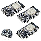
- High-performance dual-core processor – ESP32S is equipped with a powerful dual-core 32-bit CPU with a main frequency of up to 240MHz, providing smooth and efficient computing power for IoT and embedded applications.
- Wi-Fi & Bluetooth dual-mode support – Integrated 2.4GHz Wi-Fi and low-power Bluetooth, supporting wireless data transmission, remote control and smart device connection.
- Rich interfaces and functions – Provides GPIO, UART, SPI, I2C and other interfaces, supports touch sensing, infrared remote control, DAC and other functions, suitable for a variety of electronic projects.
- Low-power design – With multiple power saving modes, supports deep sleep and ultra-low power operation, suitable for battery-powered Internet of Things (IoT) devices and remote monitoring systems.
- Compatible with multiple development environments – Supports for Arduino IDE, for ESP-IDF, for MicroPython and for PlatformIO, easy to develop, suitable for beginners and advanced developers to quickly build smart applications.
WebSocket
WebSocket is useful when the receiver is a browser-based dashboard. The ESP32 can send a continuous stream without requiring the browser to poll repeatedly. Use a compact binary frame format for higher traffic rates and JSON during development when human readability is more valuable.
HTTP
HTTP is well suited to configuration pages, status endpoints, and occasional polling. It is usually a poor primary transport for a high-rate raw CAN stream because repeated request-and-response handling adds overhead and complicates continuous delivery.
MQTT
MQTT fits installations that publish frames to a broker or telemetry system. Define topic names, payload format, authentication, quality-of-service behavior, retained-message policy, and behavior during network loss. A vehicle-connected reader should not be exposed directly to an untrusted network; use appropriate network isolation and credentials.
Bluetooth
Bluetooth Classic SPP gives the original ESP32 a serial-like wireless link and can be simple for a laptop or compatible host. BLE GATT is generally more convenient for modern mobile applications. A typical BLE design uses a notification characteristic for captured frames and a write characteristic for bitrate, filter, start/stop, and status commands.
BLE packet sizes, connection intervals, throughput, and buffering limits must be tested. Do not assume that a BLE link can carry every frame from a heavily loaded bus without loss.
What the reader can and cannot tell you
The ESP32 can capture identifiers and payload bytes, but a raw capture does not automatically reveal vehicle speed, engine RPM, coolant temperature, or diagnostic trouble codes.
To interpret signals, you need one or more of the following:
The Tool Desk
Outbyte PC Repair FREERepair Windows errors before they cause bigger problemsFix Now →Outbyte Driver Updater FREEFix the driver behind crashes, sound loss and screen glitchesFind Drivers →- a DBC database;
- manufacturer or supplier protocol documentation;
- knowledge of a higher-layer protocol;
- careful reverse engineering and validation;
- a known diagnostic procedure.
Without that information, the technically accurate claim is “wireless Classical CAN frame capture,” not “wireless vehicle-data reader.” Even a known identifier may have different meanings between vehicle models, model years, ECUs, or operating modes.
Connecting to a vehicle
An OBD-II breakout cable or OBD-II-to-DB9 harness can make a bench connection more convenient, but it is not universally suitable. Verify the vehicle’s connector pinout, which CAN channel is exposed, whether the connector is powered, and how the harness routes ground and CANH/CANL.
Do not treat the diagnostic connector as permission to transmit. Keep the ESP32 in listen-only mode, avoid experimental frame injection, and disconnect immediately if the vehicle shows network faults or unexpected behavior. For a first test, a dedicated bench CAN network is safer than beginning on a running vehicle.
Rank #4

- 2.4GHz Dual Mode WiFi + Bluetooth Development Board
- Support LWIP protocol, Freertos;ESP32 is a safe, reliable, and scalable to a variety of applications
- SupportThree Modes: AP, STA, and AP+STA
- Ultra-Low power consumption, Compatible with Arduino IDE
- 1PCS 30Pin ESP32 Development Board 2.4GHz WiFi Dual Cores Microcontroller Integrated with Antenna RF Low Noise Amplifiers Filters
Testing procedure
1. Inspect the bench wiring
Before powering the circuit, verify the ESP32 voltage domain, transceiver supply, TX/RX orientation, CANH/CANL polarity, common reference where required, and termination switches. Check for shorts between CANH and CANL or either line and ground.
Recommended Free Tools
2. Test the firmware without a vehicle
TWAI loopback or self-test features can verify initialization, filtering, queue handling, and serialization. They do not prove that the external transceiver, wiring, bitrate, termination, or vehicle connection is correct.
3. Build a two-node CAN bench
Use two real CAN nodes with the same bitrate and correct termination at the two ends. Confirm that one node can transmit and the other can receive before introducing Wi-Fi or Bluetooth.
4. Capture an active bus in listen-only mode
Connect the ESP32 monitor to a known active bus with transmission disabled. Confirm that frames arrive and that the monitor does not acknowledge, inject, or otherwise alter traffic.
5. Stress the wireless path
Measure queue depth, wireless packet loss, reconnect behavior, timestamp continuity, and the result when the client disappears. Test at low and high bus utilization. A reader that works with a few frames per second may still lose data under sustained traffic.
Free tools Windows power users keep installed
One-click scans. No signup required.
6. Prepare for vehicle installation
Add protected power input, a suitable enclosure, strain relief, secure connectors, electrical protection, and a clearly documented non-transmitting operating mode. Keep the device away from pedals, steering components, hot surfaces, and locations where a loose cable could interfere with driving.
Independent reader supportYour contribution helps us test, update, and keep practical guides available for everyone.Handling overflow, errors, and disconnects
CAN reception and wireless transmission are asynchronous. A network outage must not cause the TWAI callback to wait on a socket, and a slow host must not silently consume unbounded memory.
A robust design should:
- copy frames quickly from the driver into a bounded queue;
- count dropped frames and expose the count to the host;
- include sequence numbers in wireless packets;
- separate capture timestamps from network-send time;
- close or reset dead wireless connections;
- continue or stop capture according to an explicit policy;
- report bus error and bus-off conditions;
- avoid automatic recovery that could unexpectedly change a safety-critical installation’s behavior.
If storage is available, an optional local ring buffer can preserve recent frames during a wireless outage. The device should make clear which frames were captured locally and which were successfully delivered.
Viewing and analyzing the frames
For initial debugging, a line-oriented format such as SLCAN-like text or JSON is easy to inspect with a terminal or custom script. For higher throughput, use a compact binary format with a fixed header, length field, sequence number, timestamp, identifier, flags, and payload.
What’s actually slowing this PC down?
Pick the symptom - the matching free tool is one click away.
Best Value

- 2.4GHz Dual Mode WiFi + Bluetooth Development Board
- Ultra-Low power consumption, works perfectly with the Arduino IDE
- Support LWIP protocol, Freertos
- SupportThree Modes: AP, STA, and AP+STA
- ESP32 is a safe, reliable, and scalable to a variety of applications
Desktop tools such as SavvyCAN can be useful endpoints for inspection and logging, but compatibility with a particular ESP32 wireless protocol must be implemented and verified. A CAN analysis application does not automatically understand arbitrary vehicle payloads, and a forwarded frame stream is not necessarily compatible with every CAN tool.
Readers who need more advanced capture, logging, or signal decoding can later consider a CAN bus analyzer or USB-CAN interface. That is optional: it is not required to build the wireless ESP32 reader, and commercial equipment should be selected based on the required bus type, isolation, bitrate, software, and DBC support.
Common failure modes
| Symptom | Likely causes | Checks |
|---|---|---|
| No frames received | Wrong bitrate, wrong GPIO mapping, reversed CANH/CANL, inactive bus, or missing transceiver supply | Verify the bus with a known-good tool, inspect the schematic, and test the transceiver separately |
| Errors or bus-off indications | Incorrect timing, poor wiring, missing or excessive termination, polarity errors, or CAN-FD traffic | Check bitrate, termination resistance with power removed, wiring length, and whether the bus is Classical CAN |
| ESP32 resets when Wi-Fi starts | Weak or noisy power supply, insufficient regulator capacity, or automotive transients | Use a regulated supply with suitable decoupling and protected vehicle power conversion |
| Frames appear locally but not remotely | Queue blockage, socket handling, packet framing, firewall, or client disconnect | Log queue counts and sequence numbers; test the transport independently |
| Only some frames arrive | Hardware filtering, queue overflow, BLE throughput limits, or intentionally lossy UDP | Disable filters temporarily, count drops, and test with a lower bus load |
| Vehicle behavior changes | Unexpected transmission, incorrect wiring, electrical loading, or a faulty module | Disconnect immediately, restore the original network, and do not continue vehicle testing until the cause is understood |
Practical build recommendation
For a first version, use an ESP32 board with clearly exposed GPIOs, a 3.3-V Classical CAN transceiver breakout, and Wi-Fi TCP or a simple WebSocket server. Configure TWAI for listen-only operation, use a bounded receive queue, include timestamps and sequence numbers, and display raw identifiers and bytes before attempting signal decoding.
Start on a terminated two-node bench bus. Once the capture path is reliable, test the wireless link under load. Only then connect to a vehicle through a verified harness, and retain the ability to disable or physically prevent transmission.
The Tool Desk
Outbyte PC Repair FREERepair Windows errors before they cause bigger problemsFix Now →Outbyte Driver Updater FREEFix the driver behind crashes, sound loss and screen glitchesFind Drivers →Frequently Asked Questions
Does an ESP32 have built-in CAN?
The original ESP32 has a built-in CAN-compatible controller, called TWAI by Espressif, but it does not include the CAN physical-layer transceiver. You still need an external transceiver to connect to CANH and CANL.
Can an ESP32 read CAN FD?
The original ESP32 TWAI controller supports Classical CAN, including 11-bit and 29-bit identifiers, but not CAN FD. A CAN-FD transceiver alone does not add CAN-FD capability; the controller must support CAN FD as well.
Does listen-only mode guarantee that the vehicle is safe?
No. Listen-only mode prevents intentional CAN transmission by the configured controller, but wiring faults, hardware faults, incorrect configuration, or other connected equipment can still affect the network. Treat a vehicle-connected design as safety-critical.
Can the ESP32 decode RPM or vehicle speed automatically?
No. The ESP32 can capture CAN identifiers and payload bytes. Converting those bytes into RPM, speed, temperature, or diagnostic values requires a DBC file, protocol documentation, or validated reverse engineering.
Should I add a 120-ohm resistor to the ESP32 CAN module?
Only if the reader is physically at a bus endpoint or you are building a bench network that requires it. A monitor added in the middle of an already terminated vehicle bus should normally not add another termination resistor.
The Bottom Line
An ESP32 is a capable wireless Classical CAN monitor when paired with the correct external transceiver. Build the data path as CAN bus → transceiver → TWAI → bounded queue → Wi-Fi or Bluetooth, operate in listen-only mode, verify the exact bitrate and termination, and treat raw frames as data that still requires a vehicle-specific decoding method.
Quick Recap
Product prices and availability are accurate as of the date/time indicated and are subject to change. Any price and availability information displayed on Amazon at the time of purchase will apply.