Direct answer: Rohde & Schwarz application note 1MA267 shows how to measure automotive-radar transmit waveforms and reproduce radar-to-radar interference with a millimeter-wave analyzer, IF oscilloscope, antennas and controlled signal sources. It demonstrates raised noise floors, reduced signal-to-noise ratio (SNR), missed detections and apparent close-range responses—but it is a vendor application note, not a universal radar-performance limit, regulatory certificate or vehicle-safety assessment. The hosting page’s word “Inference” is almost certainly a title error; the document consistently addresses interference tests.
The 48-page note is available from Rohde & Schwarz and was republished by All About Circuits on March 12, 2025.
As an Amazon Associate I earn from qualifying purchases.
What problem does the application note address?
Automotive radar supports collision warning, blind-spot monitoring, adaptive cruise control, lane-change assistance, rear cross-traffic alert, parking assistance and automated-driving functions. As vehicles add more 24 GHz and 76–81 GHz sensors, one transmitter can enter another receiver’s active band. Depending on frequency offset, waveform similarity, timing, bandwidth, power, antenna orientation and distance, the result can be a higher noise floor, masked targets, false detections or unstable tracking.
Do these 3 things before closing this tab:
1Fix the driver behind crashes, sound loss and screen glitches2Repair Windows errors before they cause bigger problems3Scan for outdated or missing drivers - takes under a minuteThe note discusses radar around 24 GHz and at 76, 77 and 79 GHz. Those bands describe the examples in the document, not a complete statement of current worldwide allocations or compliance requirements. Modern R&S test guidance covers 76–81 GHz in-band, out-of-band, spurious, susceptibility and radar-to-radar work: R&S automotive radar interference testing.
#1 Best Overall

- Front and Rear Detection – Cobra’s new LaserEye technology detects signals from both the front and rear of your vehicle, giving you all around protection wherever your adventures take you. Special Features: LaserEye, iRadar App
- Exclusive Shared Alerts - Connect to the Drive Smarter community to get live alerts from other drivers across the country. With Apple CarPlay & Android Auto compatibility, you can view your route and interact with alerts on your vehicle's display.
- Long Range Detection – Next generation updateable IVT Filter and advanced anti-falsing circuitry intelligently reduces false alerts from blind spot monitoring systems and other vehicle avoidance systems.
- Early Warnings – Digital Signal Processing provides faster processing for all incoming laser gun signals and rapidly provides accurate alerts, making you aware of a threat before it is right in front of you.
- Everything You Need - The Cobra RAD 480i radar detector comes with a 12V vehicle power cord, suction cup car windshield mount, and a hook and loop fastener for dash mounting, for wherever the road takes you.
Radar waveform fundamentals
CW, FMCW and chirps
Continuous-wave (CW) radar transmits a steady carrier. Frequency-modulated continuous-wave (FMCW) radar sweeps frequency, commonly with upchirps, downchirps or sequences of both. Mixing a received echo with the transmitted reference produces beat-frequency information used for range and velocity; subsequent range-Doppler processing produces detections. A near replica of the transmitted waveform can therefore land inside the receiver’s processing window and look like a target.
Chirp sequences and hopping
The note describes chirp-sequence behavior and reports typical chirp lengths of approximately 10–50 microseconds, while one 76 GHz example uses a substantially longer comparison interval. Transient analysis also reveals frequency-stepped or hopped signals in addition to the principal chirp sequence. Those values are examples, not generic radar specifications.
How the historical measurement setup works
The radar under test (RUT) transmits over the air. A horn antenna receives it, an R&S FSW signal and spectrum analyzer downconverts it to an intermediate frequency, and an R&S RTO2044 or RTO2064 oscilloscope digitizes that IF. An R&S HMP programmable supply powers the RUT. LAN or Ethernet connects the instruments, while a shared 10 MHz reference keeps the FSW and RTO coherent. The analyzer uses the B2000 analysis-bandwidth option and FSW-K60C/H transient-analysis option; FS-Z90 harmonic mixers support W-band generation or conversion in the interference setup.
What’s actually slowing this PC down?
Pick the symptom - the matching free tool is one click away.
Rank #2
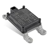
- Replace Part Numbers: 28438-5FA6A.
- Radar Sensor Fits for Nissan Altima 2.0L 2.5L 2019 2020 2021.
- Radar Sensor Fits for Nissan Rogue 2.0L 2.5L 2017 2018 2019 2020.
- Radar Sensor Fits for Nissan Rogue Sport 2.0L 2017 2018 2019 2020 2021.
- Radar Sensor Fits for Nissan Kicks 1.6L 2020 2021.
- Align the horn, RUT and receiving chain and verify the intended polarization.
- Connect the analyzer IF output to the oscilloscope and share the 10 MHz reference.
- Run the combined FSW–RTO alignment and calibration; the IF path is not ready merely because it is connected.
- Capture spectrum and time records long enough to include complete chirp sequences.
- Correlate spectrum, transient, spectrogram and signal-description views before creating an interferer.
Example analyzer settings
One 77 GHz example uses a 76.5 GHz center frequency, a 1 ms measurement time, and up to 500 MHz transient-analysis bandwidth within a 2 GHz B2000 workflow. Trace 1 uses Clear Write with an RMS detector; Trace 2 uses Max Hold with a positive-peak detector. These settings are historical examples. A current test must select center frequency, span, RBW/VBW, detector, trigger, acquisition time and analysis bandwidth from the RUT waveform and the applicable requirement.
What each measurement view tells you
- Spectrum: occupied bandwidth, chirp structure, spurious components and signals between sweeps.
- Clear Write versus Max Hold: current behavior versus the extrema observed during an acquisition; Max Hold is not a time-resolved waveform.
- RMS versus positive peak: average-power-oriented measurement versus peak excursions.
- Transient analysis: chirp duration, slope, repetition interval, idle periods and short-lived hopping.
- Spectrogram: when frequency changes occur and whether an interferer overlaps particular chirps.
In one displayed measurement, a chirp is about 198 MHz wide around 76.5 GHz and additional signals appear roughly 375 MHz from the center. Those are observations from one radar, not automotive specifications.
Interference tests in the note
24 GHz scenarios
An IMST RADAR SR-1200 observes a reflector about 12.2 m away. The note compares 50 FFT-capture cycles with and without each stimulus, using mean values.
Rank #3

- Fewer False Alerts with Cobra's Patented Technology: The IVT Filter TM system reduces false alerts from sources like collision avoidance systems so you hear only what you need to, and nothing else.
- Detects Signals From Both Front & Rear: With Cobra’s advanced laser eye sensor, you are protected from police scanning in front or behind you. Detects all radar signals (X, K and Ka bands with signal strength indication), laser and VG-2 signals
- Audible Signal Strength Levels: Unique tones provide signal strength and band identification so you can keep your eyes on the road and still identify what type of alert is detected.
- 7-Segment Color Display: High quality display features band identification icons and numeric signal strength meter for an accurate and informed drive
- Instant-On Ready: Quickly detects radar guns so you have fast speed monitoring capabilities ready to go at all times
| Stimulus | Displayed condition | What it illustrates |
|---|---|---|
| AWGN | 0 dBm and 10 dBm; 160 MHz bandwidth | Broad energy raises affected FFT bins and reduces detection margin. |
| FMCW | 0 dBm and 10 dBm; 200 MHz bandwidth; 6 ms duration | Structured, timing- and waveform-dependent distortion. |
| CW | 0 dBm and 10 dBm at 23.3 GHz | A strong localized response that can resemble a close-range target or desensitize processing. |
The 0 dBm and 10 dBm figures are stimulus settings for this demonstration, not immunity thresholds. A close-range spike can also be leakage, a room reflector, a sidelobe or a receiver-processing artifact; it is not automatically a real-world ghost target.
76 GHz scenarios
A Radarbook-based setup uses an SMW vector signal generator and SMZ90 frequency multiplier to create three cases: a time-aligned chirp, a triggered downchirp and a CW interferer near 76.23 GHz.
| Case | Reported observation | Proper interpretation |
|---|---|---|
| Time-aligned chirp | Noise floor rises; a close-target echo loses approximately 9 dB in the displayed example. | Correlated interference can consume detection margin. |
| Triggered downchirp | An approximately 14 m office-wall return remains visible but with lower SNR. | Chirp slope and timing change the coupling mechanism. |
| CW near 76.23 GHz | Spectrum noise floor increases; some targets are no longer detected. | Desensitization or masking is possible without proving a vehicle-level failure. |
The geometry, RUT, power, trigger and processing determine these results. The approximately 9 dB change is not a universal degradation number.
Rank #4
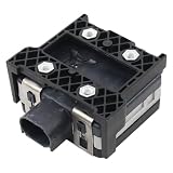
- Fit for Nissan Sentra 2017-2019
How to design a reproducible interference test
- Define the question: transmitter emissions, receiver robustness, detection performance or vehicle behavior.
- Characterize the RUT first: chirp slope, bandwidth, duration, repetition, frequency accuracy, hopping, power and antenna pattern.
- Calibrate the stimulus at the RUT: distinguish generator setting from incident OTA power and document path loss, polarization and angle.
- Control timing: sweep relative delay and trigger position; include both synchronized and unsynchronized cases.
- Use controlled echoes: preserve known range, velocity and angle while changing only the interferer.
- Measure outputs, not only RF: record detection probability, false alarms, range/velocity/angle error, track continuity and latency.
- Repeat across conditions: frequency offset, power, distance, slope, polarization, temperature and frame position.
What the note does not prove
- It is vendor-authored and demonstrates an R&S measurement architecture, not an independent comparison of instruments.
- The interferer is not always a fully matched second radar, and timing, power and waveform content are not universal.
- FFT or spectrum changes show RF or receiver-processing impact; they do not establish a probability-of-detection requirement, false-alarm rate, functional-safety violation or failed emergency-braking function.
- A missed detection in one capture is not a vehicle-level ADAS result. Conversely, seeing no ghost target does not prove immunity if the stimulus was poorly synchronized or too weak.
Failure modes worth checking
- Poor antenna alignment, uncontrolled room reflections or incorrect polarization.
- Missing common reference or incomplete FSW–RTO alignment.
- Insufficient bandwidth or acquisition time to capture the full sequence.
- Trigger instability, analyzer compression, mixer conversion-loss error or unverified calibration.
- Confusing conducted generator power with OTA incident power.
- Interference that overlaps only selected chirps or frame positions.
- Receiver saturation, range-Doppler masking, angle errors or tracker instability even when the RF trace appears acceptable.
Choosing equipment for a modern laboratory
| Test objective | Useful equipment class | Relevant example |
|---|---|---|
| Transmit waveform and spurious analysis | Wideband millimeter-wave signal/spectrum analyzer with transient and spectrogram software | R&S FSW |
| Controlled CW, AWGN and FMCW interference | Synchronized vector signal generator plus W-band conversion hardware | R&S SMW200A; the automotive page lists a dual-path configuration up to 44 GHz and 2 GHz modulation bandwidth. |
| IF digitization and time correlation | High-bandwidth oscilloscope | R&S RTP; the current family listing gives 4–16 GHz bandwidth and up to 40 Gsample/s. |
| Controlled target echoes | Radar echo generator | R&S AREG800A, listed with multiple objects and up to 4 GHz instantaneous RF bandwidth. |
| Repeatable OTA and reduced reflections | Compact antenna test range or chamber | R&S ATS1500C, described as a 1.3 m² 77/79 GHz OTA chamber. |
| Power verification | Traceable millimeter-wave power sensor | R&S NRPxxS/SN/SN-V, with models reaching 90 GHz and a family listing up to 93 dB dynamic range. |
These are demonstrated vendor solutions, not exclusive requirements. Keysight, Anritsu and NI offer other radar-test approaches, but model-level equivalence, availability and pricing require current verification. Enterprise instruments are generally quote-based; a high-end analyzer or chamber is excessive for simple classroom or low-frequency work.
Which test objective comes first?
- Transmitter characterization: prioritize frequency accuracy, occupied bandwidth, chirp slope and duration, phase noise, hopping, spurious emissions, power/EIRP and antenna pattern.
- Receiver robustness: prioritize interferer offset, waveform, bandwidth, calibrated power at the RUT, timing, polarization, angle, simultaneous echoes, detection and tracking metrics.
- Compliance: follow the applicable standard and OEM specification. The application note alone is not regulatory evidence.
- Vehicle validation: connect radar-level findings to object lists, tracker behavior and ADAS decisions under controlled and road-representative conditions.
Frequently Asked Questions
Is “Inference Tests” the correct technical term?
No. The document’s sections and experiments concern radio-frequency interference; “Inference” appears to be a title typo.
The Tool Desk
Outbyte Driver Updater FREEScan for outdated or missing drivers - takes under a minuteDriver Scan →Outbyte PC Repair FREEClear out junk files and repair common Windows errorsFree Scan →Does a raised radar noise floor prove an ADAS failure?
No. It proves interference coupling or processing impact. Vehicle-level failure requires detection, tracking and function-level evidence under the relevant safety and performance criteria.
Can the 9 dB target reduction be used as a general radar limit?
No. It is an approximately 9 dB observation from one 76 GHz radar, geometry, interferer, trigger and processing configuration.
The Bottom Line
The application note is most useful as a practical blueprint: characterize the radar waveform, build a calibrated OTA/IF chain, control interference timing and power, and measure detection outputs as well as spectra. Treat its ghost-target, SNR and missed-detection examples as demonstrations—not universal limits or proof of regulatory or functional safety.
Quick Recap
Product prices and availability are accurate as of the date/time indicated and are subject to change. Any price and availability information displayed on Amazon at the time of purchase will apply.